Table of Contents
Advertisement
Quick Links
Manual for
DMA-22(A)
Universal On-Board and Stand-Alone Digital Amplifier and Controller
DMA-22(A)-x-PN
Revision: 1.0
Applicable for SW Versions
V48.xx*
V49.xx*
(xx == 00 or higher)
HCS Hydraulic Control Systems GmbH
Neuffener Str. 29
D-72636 Frickenhausen
Telefon: (+49) 7025 - 911 007
Telefax: (+49) 7025 - 911 008
Email:
info@h-c-s-gmbh.de
Web:
www.h-c-s-gmbh.de
Germany
Manual
15.01.2024
Advertisement
Table of Contents

Related Manuals for HCS DMA-22 A Series

Summary of Contents for HCS DMA-22 A Series
- Page 1 Universal On-Board and Stand-Alone Digital Amplifier and Controller Applicable for SW Versions V48.xx* V49.xx* (xx == 00 or higher) HCS Hydraulic Control Systems GmbH Neuffener Str. 29 D-72636 Frickenhausen Germany Telefon: (+49) 7025 - 911 007 Telefax: (+49) 7025 - 911 008 Email: info@h-c-s-gmbh.de...
-
Page 2: Table Of Contents
DMA-22(A)-x-PN Revision History Revision Date Description R1.0 14.07.2022 First edition R1.0 15.07.2022 Mode 1,2 added R1.0 24.08.2022 Connection diagram changed R1.0 12.09.2022 Wiring diagrams, technical data, supply voltage range updated R1.0 30.09.2022 LED display, while Profibus timeout defined R1.0 07.06.2023 SP1..SP4 *)The designation and availability of the input depends on the module variant. - Page 3 ROFINET COMMUNICATION IS POSSIBLE ..................46 OMMUNICATION OK BUT CURRENT OUTPUTS ARE INACTIVE PNO C ..............................47 ERTIFICATE DECLARATION OF CONFORMITY........................48 NOTES: ................................. 49 HCS DISTRIBUTORS AND PARTNERS ......................49 DMA-22(A)-x-PN Manual Revision: 1.0 15.01.2024 Page: 3 of 49...
-
Page 4: General Information
1 General information About this manual This document describes the Profinet interface of the HCS digital amplifier. It describes and explains the general structure of the Profinet interface and in a second part the device specific This manual was prepared with great care and the contents reflect the author’s best knowledge. -
Page 5: Structure Of Warning Notices
After repair, certain adjustments and test procedures must be performed; this can only be made by qualified and authorized personnel. Products that need repair can be sent to the addresses: See □ Chapter „12 HCS distributors and partners„, page 49 DMA-22(A)-x-PN Manual Revision: 1.0... -
Page 6: Cleaning, Storage, Transport
This will speed up the process and guarantees a fast and reliable repair. See □ Chapter „12 HCS distributors and partners„, page 49 In the case of a fault or a malfunction, your distributor can give you instructions on the phone or in writing before accepting a repair order. -
Page 7: Technical Data
DMA-22(A)-x-PN 2 Technical data Technical data overview Table 1: Properties DMA-22(A)-x-PN Manual Revision: 1.0 15.01.2024 Page: 7 of 49... -
Page 8: Features Of The Device
Shared Device supported • Media Redundancy Protocol (MRP) supported • Used GSDML File „GSDML-V2.2-HCS-DMA-XX_PN-…….xml “ “GSDML-01F0-0002-DMA1.bmp” Programming PC Interfaces Onboard USB interface in cooperation with HCSTool or HyperTerminal. Connection diagram “Standard” The connection diagram may vary due to specific hardware or software specifications. The corresponding connection diagram for the hardware you are using is always printed on the side of the DMA module. -
Page 9: Possible Connector Options (On Customer Request)
DMA-22(A)-x-PN Possible connector options (on customer request) Options are only possible if the hardware offers the possibility! The possibility of some options is depending on the combination of all needed options. Usage Standard Option 1 Connector Output A- 1(1) Output A+ 2(2) Solenoid 4pol... -
Page 10: Front View: Address Selection And Connectors
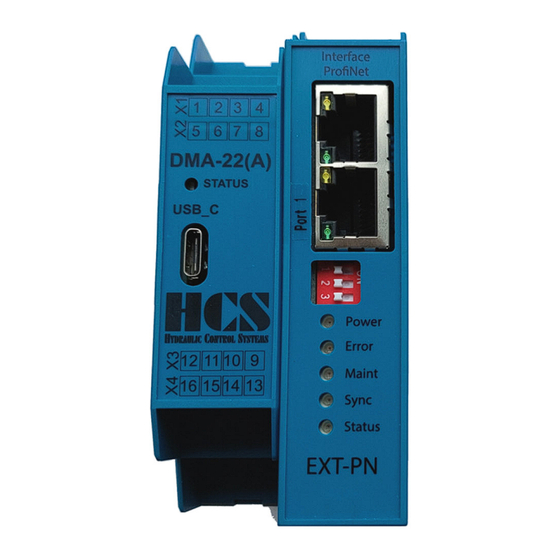
DMA-22(A)-x-PN Front View: address selection and connectors 2.9.1 Single module Version (node with one module connected) Connector Profnet Connector X1 2x Ethernet RJ45 DIP switch Connector X2 For further use LED Power: Green = OK Blinking together with LED status, Node in Config mode LED Error:... -
Page 11: Multiple Module Version (Node With Multiple Modules Connected)
DMA-22(A)-x-PN 2.9.2 Multiple module Version (node with multiple modules connected) Example: 1 Profinet-Node and 3 DMA-22(A) Modules (Slaves) connected Example: Example: Example: Defined Slave Defined Slave Defined Slave Profinet Node SADR = 1 SADR = 2 SADR = 3 (E22 = 1) (E22 = 2) (E22 = 3) Figure 3 : Connector position layout, single module... -
Page 12: General Information About Tadr (Telegram Address)
DMA-22(A)-x-PN General information about TADR (Telegram Address) TADR is a value which may be written (changed) with each cycle but changing of this value is optional and not mandatory. The value will be defined by the Profinet-Master. The purpose is to either check the telegrams by the master or also in order to force sending of a new telegram from the node. -
Page 13: Simple Commands
DMA-22(A)-x-PN 4 Simple commands CMD 3 Master Read 4.1.1 CMD = 3, Master Read parameters (7 bytes) Write first… Byte Abbreviation Description TADR Telegram address, defined by the user, Range 0..255, 0..0xFF SADR Slave address Command: 3 = Read multiple parameters by the master High byte parameter ID of first parameter Low byte parameter ID of first parameter N-high... -
Page 14: Cmd = 3, Error From Slave (4 Bytes)
DMA-22(A)-x-PN 4.1.3 CMD = 3, Error from Slave (4 bytes) Write first… Byte Abbreviation Description TADR Telegram address, defined by the read command, Range 0..255, 0..0xFF SADR Slave address Error code EXCE Exception …Write last Error code: 0x83 = Read failed EXCE Exception: 1 = Command not supported... -
Page 15: Cmd = 6, Master Write
DMA-22(A)-x-PN CMD = 6, Master Write 4.3.1 CMD = 6, Master Write single parameter (7 bytes) Write first… Byte Abbreviation Description TADR Telegram address, defined by the user, Range 0..255, 0..0xFF SADR Slave address Command: 6 = Write single parameter by the master High byte parameter ID Low byte parameter ID DATH... -
Page 16: Cmd = 6, Error From Slave (4 Bytes)
DMA-22(A)-x-PN 4.3.3 CMD = 6, Error from Slave (4 bytes) Write first… Byte Abbreviation Description TADR Telegram address, defined by the write command, Range 0..255, 0..0xFF SADR Slave address Error code EXCE Exception …Write last Error code: 0x86 = write failed EXCE Exception: 1 = Command not supported... -
Page 17: Example, Write Set Value
DMA-22(A)-x-PN 4.4.2 Example, write set value Examples for set value via Profinet (ID = 0x0027): 1.) Command signal 0.000 V = 0x0000: Byte Data Abbreviation 0x12 TADR 0x01 SADR 0x06 0x00 0x27 0x00 DATL 0x00 DATH 2.) Set value 5.000 V = 0x1388: Byte Data Abbreviation... -
Page 18: Complex Commands
DMA-22(A)-x-PN 5 Complex commands CMD = 15, Master writes multiple parameters (3+5·module bytes) (Fast multi-slave command) Parameter E22 in the related DMA-22(A)-module has to be set to the correct value within the range of 1 to 5 depending on the number of connected slaves (modules). The slave at the left side has the address „1” and the slave closest to the Profinet node will have the highest address setting. -
Page 19: Cmd = 15, Response From Slave (9 Bytes)
DMA-22(A)-x-PN CMD = 15, Response from Slave (9 bytes) Please pay attention to the fact that in case of multiple slave operation SADR will be changed automatically with each new response. Example: When using 3 slaves than the slave with the module address „1” (E22 = 1) will respond first. After the next „Master-Write”... -
Page 20: Examples , Cmd = 15
DMA-22(A)-x-PN Examples, CMD = 15 5.4.1 Single slave The Profinet Address Selector in front of the Profinet-Node is set to the right value (bus error LED is off). E22 of the DMA-22(A) module is set to 1. Hardware Enable is connected to the DMA-22(A) module. Master writes set value of 1.000 V to slave (module): Byte Data... - Page 21 DMA-22(A)-x-PN Response telegrams are automatically multiplexed by the DMA-22(A)-Profinet node. In this example, module 1 answers first Byte Abbreviation Abbreviation Description 0x23 TADR Response telegram address (defined by the write command) 0x01 SADR Actual slave address 0x0F 0x0F in decimal 15 0x40 DAT1.1H High byte of module state, Hardware Enable is active, no error...
-
Page 22: Cmd = 15, Structure Of Profinet Telegram Definition, Depending On Sw Versions
DMA-22(A)-x-PN CMD = 15, structure of Profinet telegram definition, depending on SW Versions 5.5.1 General Error Message (indication by „Error occurred”) Errors which are indicated in the Bit (Error occurred) like for example „Over Current” or „Cable Fraction” can be reset with the following action : Set input signal for the hardware enable at the according module at terminal X3/1 (9) to „Low”... -
Page 23: Explanation Of Special Functions And Module State Bits
DMA-22(A)-x-PN Explanation of special functions and module state bits Attention: Functions and module state bits depend on the used SW version HW_ENABLE The „Enable” signal (HW Enable X3/1 (9)) is activated at the module. ERROR An Error has occurred in the DMA module. Different possible problems can cause this. Please refer to the manual for the according DMA version. -
Page 24: Version For Mode 1 (Open Loop, One Valve With Two Solenoids)
DMA-22(A)-x-PN 5.5.2 Version for Mode 1 (open loop, one valve with two solenoids) Telegram structure example with 1 DMA module (SNUM = 1), Master writes multiple parameters (3+5·module bytes) Write first… Comment Byte Structure Abbreviation Description TADR Telegram address, defined by User, Range 0..255, 0..0xFF Telegram SNUM Number of connected slaves (Maximum 5) -
Page 25: Version For Mode 2 (Open Loop, Two Valves With One Solenoid Each)
DMA-22(A)-x-PN 5.5.3 Version for Mode 2 (open loop, two valves with one solenoid each) Telegram structure example with 1 DMA module (SNUM = 1), Master writes multiple parameters (3+5·module bytes) Write first… Comment Byte Structure Abbreviation Description TADR Telegram address, defined by User, Range 0..255, 0..0xFF Telegram SNUM Number of connected slaves (Maximum 5) -
Page 26: Version For Mode 3, 4, 10 (Closed Loop)
DMA-22(A)-x-PN 5.5.4 Version for Mode 3, 4, 10 (closed loop) Telegram structure example with 1 DMA module (SNUM = 1), Master writes multiple parameters (3+5·module bytes) Write first… Comment Byte Structure Abbreviation Description TADR Telegram address, defined by User, Range 0..255, 0..0xFF Telegram SNUM Number of connected slaves (Maximum 5) -
Page 27: Version For Mode 6, 11 (Two Closed Loops)
DMA-22(A)-x-PN 5.5.5 Version for Mode 6, 11 (two closed loops) Telegram structure example with 1 DMA module (SNUM = 1), Master writes multiple parameters (3+5·module bytes) Write first… Comment Byte Structure Abbreviation Description TADR Telegram address, defined by User, Range 0..255, 0..0xFF Telegram SNUM Number of connected slaves (Maximum 5) -
Page 28: Version For Mode 8 (Closed Loop)
DMA-22(A)-x-PN 5.5.6 Version for Mode 8 (closed loop) Telegram structure example with 1 DMA module (SNUM = 1), Master writes multiple parameters (3+5·module bytes) Write first… Comment Byte Structure Abbreviation Description TADR Telegram address, defined by User, Range 0..255, 0..0xFF Telegram SNUM Number of connected slaves (Maximum 5) -
Page 29: Digital Inputs
DMA-22(A)-x-PN Digital inputs The DMA-22(A) has three digital inputs Connector Enable Digital input 0 X3 / 9 signal Connector Set Value X4 / 13 S1.01 Digital input 1,2 Connector Set Value X4 / 14 S1.02 Figure 4: Digital inputs 5.6.1 Digital input 0 (enable signal) input 1,2 (set Value selection) The digital enable signal incorporates the following functions: Removes the hardware locking of the output stages •... -
Page 30: Digital Outputs
DMA-22(A)-x-PN Digital outputs The following digital output is available. Error output Digital Output Connector Error / Comp. X12 / 10 ComparatorX output Dout_X output E 18 Figure 7: Digital outputs 5.7.1 Digital output: \Error or Comparator output At the terminal X12 / 10 the error output or comparator is available (Depending on setting E18) If an error occurred, the output is low (negative logic). -
Page 31: Status Display Leds
DMA-22(A)-x-PN Status display LEDs The network and the amplifier states are indicated by light emitting diodes (status display LEDs) on the electronics housing. green / yellow / red USB Port Figure 10: Top view, status LEDs and USB Port 5.8.1 LED definition Definition constantly ON constantly OFF... -
Page 32: Plc Configurator
DMA-22(A)-x-PN 6 PLC configurator Module catalog: Please select the “IN/OUT 42 byte Rev……” module. Automatically an 42 byte in- output buffer will be reserved. So all kind of DMA module configuration can processed. And insert this module into the bus structure. Device details: DMA-22(A)-x-PN Manual... -
Page 33: Configuration For Siemens Tia Portal
DMA-22(A)-x-PN 7 Configuration for SIEMENS TIA portal Two Profinet function blocks for the Siemens TIA portal are available, and can be downloaded from the HCS web side. Which one, the user should take, is depending on the used CPU family. - Page 34 DMA-22(A)-x-PN Add new “Distributed I/O” and connect The DMA to the network. DMA-22(A)-x-PN Manual Revision: 1.0 15.01.2024 Page: 34 of 49...
-
Page 35: Assign The Io-Module From The Gsd To The Device
DMA-22(A)-x-PN Assign the IO-Module from the GSD to the device Install the function block Add new external file, Chose the function block according your used CPU series • Siemens CPU series S7-300,400 PN_DMA_2_CLASSIC_DB(Vxx).scl • Siemens CPU series S7-1200,1500 PN_DMA_2_DB.scl(Vxx).scl Right click on the selected file and “Generate blocks from the source” After generation the functionsblock is now available DMA-22(A)-x-PN Manual... -
Page 36: Explanation Of The Function Block
DMA-22(A)-x-PN Explanation of the function block 7.4.1 General In this chapter we describe, how to use the function block in the different modes. The structure and function for CMD 3, CMD 6 is the same in every working mode of the DMA-2. Only the CMD 15 differs depending on the DMA-2 operation mode. -
Page 37: Classic Cpu 300,400: Definition Of The Data Buffer Address
DMA-22(A)-x-PN 7.4.2 Classic CPU 300,400: Definition of the data buffer address Unlike the CPU 1200, 1500, the E-address and A-address must be assigned to the variables #ADR_IN and #ADR_OUT here. The data buffer address #ADR_IN, #ADR_OUT is predefined to 256. Please check the correct address of your system and change the value if necessary. -
Page 38: Cmd 3, Reading Values From One Dma-2 Node
DMA-22(A)-x-PN Please check the correct IP address of the device and change the value if necessary. 7.4.4 CMD 3, Reading values from one DMA-2 node Every DMA-2 module connected to the Profinet node has an own SNUM (slave number). Together with this number it is possible to read an set of parameter of this specific DMA-2. -
Page 39: Cmd 6, Writing Parameters To One Dma-2 Node
DMA-22(A)-x-PN • Start the process, by writing #CMD3_STAT := 1; (CMD_START) • When #CMD3_STAT reaches the value 4 (CMD_FINISH), Reading is finished, and the values can be read in the structure #OUT_CMD.VALUE[1..8]. In addition the number of received bytes will be shown I the structure #OUT_CMD.CNT. -
Page 40: Cmd 15, Writing And Reading Once To All Connected Dma Nodes
DMA-22(A)-x-PN 7.4.6 CMD 15, Writing and Reading once to all connected DMA nodes The CMD 15 makes it possible to send and receive process data from all DMAs connected to the Profinet node. In this case, the variable SNUM (slave number) contains the maximum number of connected DMA-2s. (deviating from CMD 3 or CMAD6). -
Page 41: List Of Parameters
DMA-22(A)-x-PN 8 List of parameters Parameters in grey letters are not yet implemented in the DMA Software. All values in decimal, for usage as data values they must be converted into Hex R = read only parameter. X = implemented, but not active (no access) W/R = writing and reading possible. - Page 42 DMA-22(A)-x-PN W/R Name Function Unit Def Description 0x2D 45 R/W C1.04 Gain B 100 100 == Factor 1.00 0x2E 46 R/W C1.05 Set value sign and gain -400 100 100 == Factor 1.00 Sign and gain! 0x2F 47 R/W C1.06 Set value offset -9999 9999 0 -1000 == -1.000 V;...
- Page 43 DMA-22(A)-x-PN W/R Name Function Unit Def Description 0x4B 75 R/W C2.07 Dead band compensation A 9999 0 1000 == 1.000 V 9.999 V = max. current depending on solenoid 0x4C 76 R/W C2.08 Dead band compensation B 9999 selection 0x4D 77 R/W C2.09 Sensor type 4 off = Deactivated 1 = 0...20mA...
- Page 44 DMA-22(A)-x-PN W/R Name Function Unit Def Description 0x63 99 R P-Portion current contr. Energization A 9999 500 Default for 2,700 A solenoid E1.04 0x64 100 R I-Portion current contr. Energization A 9999 E1.05 0x65 101 R P-Portion cur. contr. de- energization A 1300 9999 1300...
- Page 45 DMA-22(A)-x-PN W/R Name Function Unit Def Description 0xAF 175 R/W C2.32 Comparator selection Comp_22 0 0 = off 1 = Set value 2 = Actual value 3 =Lag error 0xB0 176 R/W E Int Internal Digital Switches (Read/Set) 0xFFFF 0x0001 = Din_1 active (Read/Write) 0x0002 = Dout_1 active (Read only ) 0x0004 = Comp_1 active (Read only ) 0x0008 = Comp_11 active (Read only )
-
Page 46: Troubleshooting
DMA-22(A)-x-PN W/R Name Function Unit Def Description 0x103 259 R/W L2.y5 Linearization curve [5,5] 9999 6250 0x104 260 R/W L2.x6 Linearization curve [6,6] 9999 7500 0x105 261 R/W L2.y6 Linearization curve [6,6] 9999 7500 0x106 262 R/W L2.x7 Linearization curve [7,7] 9999 8750 0x107... -
Page 47: Pno Certificate
DMA-22(A)-x-PN PNO Certificate DMA-22(A)-x-PN Manual Revision: 1.0 15.01.2024 Page: 47 of 49... -
Page 48: Declaration Of Conformity
10 Declaration of Conformity EC Declaration of Conformity in accordance with EMC Directive 2014/30/EU HCS Hydraulic Control Systems GmbH Neuffener Str. 29 D-72636 Frickenhausen Hereby declares that the product described as follows complies in terms of its design, as well as in the version placed in the stream of commerce by us, with the relevant requirements of the directive. -
Page 49: Notes
DMA-22(A)-x-PN 11 Notes: HCS distributors and partners Please refer to: https://www.h-c-s-gmbh.de/en/sales-partners on our web side. - End - DMA-22(A)-x-PN Manual Revision: 1.0 15.01.2024 Page: 49 of 49...
Need help?
Do you have a question about the DMA-22 A Series and is the answer not in the manual?
Questions and answers