Table of Contents
Advertisement
Quick Links
INSTRUCTIONS
Type 1433
DECADE RESISTOR
6
6
6
o;,,c•<Pc
"""'
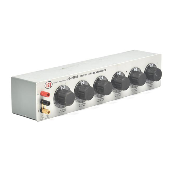
Figure 1-1. Type 1433-T Decade Resistor.
6
DIV 57
INSTB.UJIIIENT POOL
LIBRARY
SPECIFICATIONS
Long-Term Accuracy: Our two-year warranty applies to the toler-
ances given below unless the resistor is damaged by excessive
current. These tolerances apply for low-current measurement at
de or low-frequency ac (see below},
Over-all Accuracy: The resistance difference between that at any
setting and at the zero setting is equal to the indicated value
:=:(0,02%
+
2
ma).
Incremental Accuracy: See tab!e. This is the accuracy of the
change in resistance between any two settings on the same dial.
Max Current: The max current for each decade is given in the
table below and also appears on the pane! of each decade box
and on the dial plate of each decade resistance unit.
Frequency Characteristic:
Refer to
Section 3.
Zero Resistance (Ro):
0.001
Q
per dial at dc1 0.04 O per dial at
1 MHz; proportional to square root of frequency at all frequen-
cies above 100 kHz.
Temperature Coefficient of Resistance: Less than ±10 ppm per
degree C for values above 100
Q
and ±20 ppm per degree C for
100
Q
and below, at room temperatures. For the 1433's the box
wiring will increase the over-all temperature coefficient of the
0.1- and 0.01-0 decades.
Switches: Quadruple-leaf brushes bear on lubricated contact studs
of :Vs-in, diameter in such a manner as to avoid cutting but yet
give a good wiping action. A cam-type detent is provided. There
are eleven contact points {O to 10 inclusive). The switch resist•
ance is !ess than 0.0005
Q,
The effective capacitance is of the
order of 5 pF, with a dissipation factor of 0.06 at 1 kHz for the
DECADE
RESISTOR
Type 1433
DECADE·
RESISTANCE
UNITS
Type 510
Catalog Number
I
Bench
Rack
Type
1433-9700
1433-9701
1433-U
1433-9702
1433-9703
1433·K
1433-9704
1433-9705
1433-J
1433-9706
1433-9707
1433-L
1433-9708
1433-9709
1433-Q
1433-9710
1433-9711
1433-T
1433-9712
1433-9713
1433-N
1433-9714
1433-9715
1433-M
1433-9716
1433-9717
1433-P
1433-9718
1433-9719
1433·Y
1433-9720
1433-9721
1433-W
1433-9722
1433-9723
1433-X
1433-9724
1433-9725
1433-B
1433-9726
1433-9728
1433-Z
1433-9729
1433-9730
1433-F
1433-9731
1433-9732
1433-G
1433-9733
1433-9734
1433-H
Total
Resistance
Type
Ohms
510-AA
0.1
510-A
l
510-8
10
510-C
100
510-0
1000
510-E
10,000
51 O·F
100,000
510-G
1,000,000
510-H
10,000,000
*Or a max of 4000 V, pk.
standard ce!!ulose-filled molded phenolic switch form and 0,01 on
the mica-filled phenolic form used in the 510-G and 510-H units.
Max Voltage to Case: 2000 V pk,
Terminals: For 1433, low-thermal-emf jack-top binding posts on
standard .;\/4-in. spacing. Shield terminal is provided.
soldering
lugs for rear connection.
Mounting:
1433's in
lab-bench
cabinet, rack
models
include
mounting hardware; 510's complete with dial plate, knob, tem-
plate, and mounting screws.
Dimensions and Weights: in. (mm), lb {kg):
4-dial
5-diaJ
6-dlal
i
7-dial
U, K,
J,
L, Q
T,N,M,P,Y
W, X, B,Z
F, G, H
Width*
12¼. {315)
I
14¥4 (375)
17¼ (445)
Height
3½(89)1
I
5¼ (135)
Depth
5 in. over-at!, 4 in. behind panel
Net Wt
4¥4 {2.2)
I
5¾ (2.7)
I
7 (3.2)
I
83/4 (4.0)
Ship. Wt
51/2 (2.5)
I
61h {3.0)
I
a½ (3.9)
I
10¼ (4.7)
"Data given for bench models. All rack models same except 19 in. wide.
Add approx 1 !b for rack-mount hardware.
Type 510's 3¼
6
in. (78 mm) diameter, 3?{
0
in. (85 mm) behind
pane!, 11 oz (0.4 kg) net weight.
Ohms
pee
No. of
Type 510 Decades
Total Ohms
Step
Dials
Used
111.1
0.01
4
AA,A, B,C
1111
0.1
4
A,8,C,D
11,110
l
4
8, C, D, E
111,100
10
4
C,D, E,F
1,111,000
100
4
D,E, F,G
1111.1
0.01
5
AA, A, B,C,D
11,111
0.1
5
A, B,C,D,E
111,110
l
5
8, C, D, E, F
1,111,100
10
5
C, D, E, F, G
11,111,000
100
5
D, E, F,G,H
11,111.1
0.01
6
AA,A, B,C,D, E
111,111
0.1
6
A, 8, C, D, E,-F
1,111,110
l
6
8, C, D, E, F, G
11,111,100
10
6
C,D,E,F,Q, H
111,111.1
0.01
7
AA, A, 8, C, D, E, F
1,111,111
0.1
7
A,B,C,D,E,F,G
11,111,110
l
7
8, C, D, E, F, G, H
Resistance
I
Accuracy of
Max
Power
Per Step
Resistance
Current
Per Step
Al
(M)'Ohms
Increments
40" C Rlse
Watts
µH
0.01
±2%
4
A
0.16
0,01
0.1
±0.4°/o
1.6 A
0.25
0.014
l
±0,1%·
I
800
mA
0.6
0,056,
10
±0.04%
250
mA
0.6
0.11
100
±0.02%
80
mA
0.6
0.29
1000
±0.02%
23
mA
0,5
13
10,000
±0.02%
7
mA
0.5
70
100,000
±0.02%
2.3 mA
0.5
-
1,000,000
:±:::0,02%
0.7* mA
0.5
-
Advertisement
Table of Contents


Need help?
Do you have a question about the 1433 and is the answer not in the manual?
Questions and answers