Table of Contents
Advertisement
Quick Links
Advertisement
Table of Contents

Subscribe to Our Youtube Channel
Related Manuals for Barco CDMS-3739


Summary of Contents for Barco CDMS-3739
- Page 1 Component Maintenance Manual CDMS-3739 (A03X) K5920074-01 06 July 2011 Barco n.v. President Kennedypark 35 - 8500 Kortrijk (Belgium) Tel. +32 (0)56 23 32 11 - Fax +32 (0)56 23 35 88 H.R. Kortrijk 149.094 - BTW BE 473.191.041 Fortis Bank 285-0480090-66...
-
Page 2: Important Notice
15 minutes. If any symptoms are present after washing, get medical care. The material in this manual consists of information that is the property of Barco n.v. and is intended only for internal Barco use. The unit contains material in which Barco retains proprietary rights. Any act involving software reproduction or intervention is prohibited. -
Page 3: Table Of Contents
K5920074-01 Barco Proprietary Information Table of contents Table of contents 1 Introduction......................2 1.1 General ...................... 2 1.2 How to use the manual ................. 2 2 Description and operation ..................4 2.1 General ...................... 4 2.2 Configuration overview ................. 4 2.3 Mechanical description.................. - Page 4 K5920074-01 Barco Proprietary Information Table of contents 8.5 Installation of the main processor board ............50 8.6 Installation of the power supply ..............50 8.7 Installation of the fan module ..............50 8.8 Installation of the interconnection board ............51 9 Special tools and equipment ..................
- Page 5 K5920074-01 Barco Proprietary Information List of figures List of figures Figure 1: Interface diagram ..................5 Figure 2: CDMS software architecture ................ 19 Figure 3: Start-up page CDMS - example ..............22 Figure 4: Highest priority page – example ..............22 Figure 5: Maintenance cable ..................
-
Page 6: List Of Tables
K5920074-01 Barco Proprietary Information List of tables List of tables Table 1:Signal list connector J1 ................... 8 Table 2:Messages ....................24 Table 3:Parts list ..................... 61 Barco n.v. President Kennedypark 35 Page iv of iv B-8500 Kortrijk, Belgium www.barco.com... -
Page 7: Record Of Revisions
K5920074-01 Barco Proprietary Information Record of revisions Issue, Release date Description 00, 23 March 2010 Initial release. 01, 7 July 2011 Update applicability A03X. Update installation drawing. Barco n.v. President Kennedypark 35 Page 1 of 63 B-8500 Kortrijk, Belgium www.barco.com... -
Page 8: Introduction
(SRU). IMPORTANT The procedures, instructions and information given in this CMM are only for approved persons with the necessary skills. Repair activities may only be performed by Barco approved personal. How to use the manual •... -
Page 9: Important Notes
K5920074-01 Barco Proprietary Information Introduction CAUTION Cautions – presented in this manual, provide information, which if not adhered to, may result in damage to the equipment. NOTE Notes – presented in this manual, provide information, which emphasize points, significant to understand the unit. -
Page 10: Description And Operation
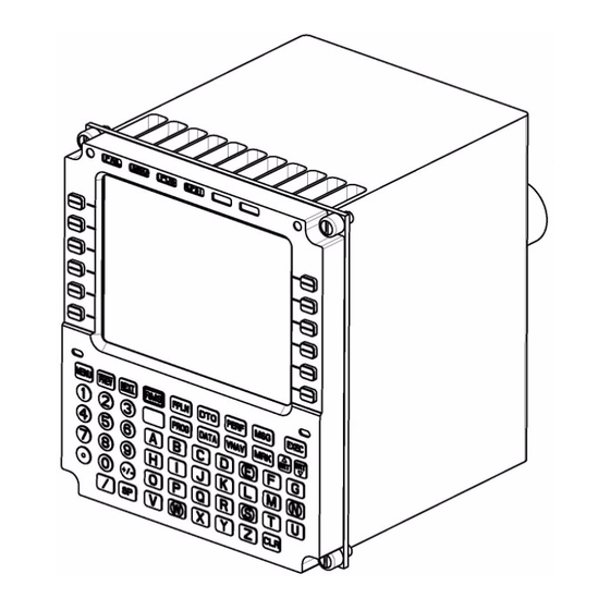
K5920074-01 Barco Proprietary Information Description and operation Description and operation General The CDMS acts as a slave text terminal for ARINC739A compatible avionics equipment. The CDMS provides for aircrew data entry, avionics mode selections and system status display. The CDMS consists of a push-button keyboard, with sunlight readable annunciators indicating pending actions, and a multi-function alphanumeric display, capable of displaying 14 lines of 24 characters. -
Page 11: Interfaces
Main processor board (2-102) • Power supply (2-103) • Fan module (2-104) • Interconnection board (2-105) • Unit cover CDMS-3739 (3-101) Interfaces 2.4.1 The system interfaces The picture below shows the general interface diagram Figure 1: Interface diagram Interface description •... -
Page 12: External Connectors
The external connector is identified in Figure C-1-2. Connector J1: 55 pin male receptacle connector D38999/20FE35PN, mating connector D38999/26FE35SN. NOTE The maintenance connector is intended only for maintenance use by Barco personnel and service centers. Barco n.v. President Kennedypark 35... - Page 13 K5920074-01 Barco Proprietary Information Description and operation Connector J1 Pin # Signal type Signal label Spare Spare Discrete input Reserved 28 V 28VDC 28 V 28VDC 28 V Return 28VDC_RET 28 V Return 28VDC_RET 0-5V DC KeyBklDim_Hi 0-5V DC return...
-
Page 14: Signal Description
GNDM Table 1: Signal list connector J1 IMPORTANT CDMS-3739-A03X does not support NVG capabilities. Therefore A/C wiring must be such that Day/nNight discrete is OPEN and NVG discrete is OPEN NOTE Where indicated RESERVED or SPARE this must be interpreted as: RESERVED: Pin is connected internally, but may not be used in this configuration. - Page 15 K5920074-01 Barco Proprietary Information Description and operation The maximum current in normal operation is 1.429 A (= 40 W / 28 V). The maximum inrush current is: • up to 1 ms: less than 20 times the normal current (28.6 A), •...
-
Page 16: Electrical Description
K5920074-01 Barco Proprietary Information Description and operation The fail annunciator is directly connected to the nFail discrete. During start-up of the unit, the fail annunciator is also temporarily disabled. Light Sensor Enable The Keyboard and Display Assembly of the CDMS contains ambient light sensors which adjust screen brightness depending on ambient light conditions. -
Page 17: Motherboard
K5920074-01 Barco Proprietary Information Description and operation 2.5.2 Motherboard Block diagram The block diagram of the motherboard is shown in Figure B-3-1. Description The motherboard contains several connectors to make the interconnections between: • Interconnection board • Vivaldi board •... - Page 18 K5920074-01 Barco Proprietary Information Description and operation Watchdog timer Peripheral Component Interface (PCI) bridge and arbiter Memory controller for Synchronous Dynamic Random Access Memory (SDRAM), Flash, Ferroelectrics Random Access Memory (FRAM) and Field Programmable Gate Array (FPGA) accesses Discrete control •...
-
Page 19: Vivaldi Mezzanine
K5920074-01 Barco Proprietary Information Description and operation • A dedicated test connector that contains: A JTAG and JTAG/COP interface for test purpose, Direct I²C access to an ETI chip, I²C access to the configuration I²C bus. • A 100 MHz crystal oscillator distributing following clock signals: Central processing unit MPC8270 (31.25 MHz) -
Page 20: Power Supply
K5920074-01 Barco Proprietary Information Description and operation 2.5.4 Power supply Block diagram The block diagram of the power supply is shown in Figure B-5-1. Description Following functions are provided by the power supply: • generating all required internal power voltages ((+1.5V, +3.3V, +5V, +12V and -12V) •... -
Page 21: Front Assembly
K5920074-01 Barco Proprietary Information Description and operation • Ethernet channel 1 is routed towards connector J18 and is only used during maintenance and development. • 10 Open / Ground discrete inputs. All of the inputs are routed to discrete input buffers. Then the main processor board reads out the resulting state via I²C from an I/O expander. -
Page 22: Kdbc
K5920074-01 Barco Proprietary Information Description and operation Description The panel module contains the Active Matrix Liquid Crystal Display (AM-LCD). 2.5.6.3 KDBC 2.5.6.3.1 KDBC baseboard Block diagram The block diagram of the KDBC baseboard is shown in Figure B-7-3. Description Following functions are provided by the KDBC baseboard: •... -
Page 23: 2.5.6.3.2 Kdbc Mezzanine
K5920074-01 Barco Proprietary Information Description and operation Heater Time Out (Htr TriggerLine signal via I/O Expander switch off tran- sistor) Power switch (NHeaterPowerPresent signal determinates by LCDHeater_h) • A dedicated keyboard scanning component to scan the keyboard for key presses. Key press information is communicated towards the ARM via SPI decoding. -
Page 24: Keyboard Assembly
K5920074-01 Barco Proprietary Information Description and operation • Decoupling capacitors for all power supply rails. 2.5.7 Keyboard assembly The Keyboard contains the actual switches, annunciators and other mechanical parts (key caps, bezel…). Keyboard scanning is performed by the scanning circuitry on the KDBC. -
Page 25: Figure 2: Cdms Software Architecture
Inter processor interface The Inter processor Interface consists of a high speed serial line between the ARM-7 micro controller and the MPC8270 processor. The CDMS uses the “Barco Avionics Communication Protocol- Extended Performance” to communicate between the MPC 8270 and the Arm 7. -
Page 26: Start-Up Sequence
K5920074-01 Barco Proprietary Information Description and operation • Communication with the MPC 8270. The look-up tables, in the KDBC, provide a mapping between the input voltage (0 to 5 volts) for the keyboard and annunciator brightness controls, and the actual brightness of the keyboard and annunciators, respectively. -
Page 27: Cold Start
K5920074-01 Barco Proprietary Information Description and operation At power-up, the CDMS software interrogates the hardware to know whether the start is a cold or warm start. Cold start A cold start is a condition in which PBIT and highest priority port communication are performed. -
Page 28: Figure 3: Start-Up Page Cdms - Example
K5920074-01 Barco Proprietary Information Description and operation Figure 3: Start-up page CDMS - example The underlined configuration will be loaded. Warm start A warm start is a condition in which neither PBIT nor highest priority port communication are performed, thus allowing the CDMS to provide its main functionality much faster. -
Page 29: Built-In-Test
K5920074-01 Barco Proprietary Information Description and operation First, the CDMS listens on ports 1 and 2 for incoming SSID messages. Ports 1 and 2 are connected to a "primary" subsystem and a "secondary" subsystem. The mapping between a port and "primary" or "secondary" sub-system is configurable. - Page 30 K5920074-01 Barco Proprietary Information Description and operation illuminates all annunciators, with exception of the non-operational spare annunciators. IBIT completes in 30 seconds or less. CBIT The CDMS performs CBIT as a background task when it does not execute any other task such as PBIT, key handling, or communications with subsystems.
- Page 31 K5920074-01 Barco Proprietary Information Description and operation In normal case when there is no failure, the discrete pin is internally pulled low. The fail discrete will be set as a result of failures with operational effect. Barco n.v. President Kennedypark 35...
- Page 32 K5920074-01 Barco Proprietary Information Description and operation BIT failure identification BIT n° System ele- Potential Failure Potential Potential Failure Effects on ment function Modes Causes of Failure Component Subsystem System (X's) G01_F01 3V3 DC/DC Con- Erroneous +3,3V Component Erroneous Erroneous...
- Page 33 K5920074-01 Barco Proprietary Information Description and operation BIT n° System ele- Potential Failure Potential Potential Failure Effects on ment function Modes Causes of Failure Component Subsystem System (X's) G01_F02 Monitoring cir- Erroneous I²C bus Component Erroneous I²C Erroneous Moni- Erroneous Moni-...
- Page 34 K5920074-01 Barco Proprietary Information Description and operation BIT n° System ele- Potential Failure Potential Potential Failure Effects on ment function Modes Causes of Failure Component Subsystem System (X's) G01_F08 Monitoring cir- Loss of Tacho_2 sig- Component Loss of Tacho_2 Loss of Fan 2...
- Page 35 K5920074-01 Barco Proprietary Information Description and operation BIT n° System ele- Potential Failure Potential Potential Failure Effects on ment function Modes Causes of Failure Component Subsystem System (X's) G04_F01 Discrete I/O Erroneous Discrete Component Erroneous OPEN Loss of Lamp Loss of Lamp...
- Page 36 K5920074-01 Barco Proprietary Information Description and operation BIT n° System ele- Potential Failure Potential Potential Failure Effects on ment function Modes Causes of Failure Component Subsystem System (X's) G10_F02 Video RAM Data corruption of Component Data corruption Erroneous Video Degraded dis-...
- Page 37 K5920074-01 Barco Proprietary Information Description and operation BIT n° System ele- Potential Failure Potential Potential Failure Effects on ment function Modes Causes of Failure Component Subsystem System (X's) G11_F03 Buffers address Short circuit on ad- Component Short circuit on Loss of Flash,...
- Page 38 K5920074-01 Barco Proprietary Information Description and operation BIT n° System ele- Potential Failure Potential Potential Failure Effects on ment function Modes Causes of Failure Component Subsystem System (X's) G13_F15 LCD Tempera- Loss of LCD- Component Loss of LCD Loss of LCD tem-...
- Page 39 K5920074-01 Barco Proprietary Information Description and operation BIT n° System ele- Potential Failure Potential Potential Failure Effects on ment function Modes Causes of Failure Component Subsystem System (X's) G13_F17 NVRAM memory Erroneous NVRAM Component Erroneous Reduced display Degraded dis- failure...
- Page 40 K5920074-01 Barco Proprietary Information Description and operation BIT n° System ele- Potential Failure Potential Potential Failure Effects on ment function Modes Causes of Failure Component Subsystem System (X's) G22_F01 Connections to Loss of Ngo_Viv sig- Component Fail signal is Activation of...
-
Page 41: Testing And Fault Isolation
K5920074-01 Barco Proprietary Information Testing and fault isolation Testing and fault isolation The fault find tree below shows the different steps to identify the defective SRU. The repair activity consists of replacing the defective SRU. A repair activity is completed after a final successful ATP. Any ATP failure after repair shall lead to a new investigation and repair. -
Page 42: Disassembly
K5920074-01 Barco Proprietary Information Disassembly Disassembly Equipment and materials • Caliber CAL00579. Removal of the cover 1. Loosen the 2 screws (10-100) of the ECRO cover plate at the back of the unit (see Figure C-2-1). 2. Remove the ECRO cover plate (3-100) 3. -
Page 43: Removal Of The Main Processor Board
K5920074-01 Barco Proprietary Information Disassembly 5. Loosen the 2 screws (10-102); remove the 2 washers (11-100) and the 2 washers (11-101) at the front side of the front assembly (see Figure C-4-2). 6. Loosen the 2 screws of the KDBC connector with hexagonal bit HOP2 (see Figure C-4-2). -
Page 44: Removal Of The Interconnection Board
K5920074-01 Barco Proprietary Information Disassembly 3. Loosen the screw (10-104), remove washers (11-102) and (11-103) at the left side of the unit (see Figure C-7-1). 4. Loosen the 2 screws (10-105) at the right side of the unit (See Figure C-7- 5. -
Page 45: Cleaning
K5920074-01 Barco Proprietary Information Cleaning Cleaning WARNING Use cleaning agent away from flames or hot surfaces. Use gloves and protective goggles to prevent hand and eye injuries. 1. Make sure the unit is in the "power off" mode. Cleaning the LCD panel Dust, fingerprints, grease etc. - Page 46 K5920074-01 Barco Proprietary Information Cleaning CAUTION Do not use: - lye or cleaning solutions containing lye; - acid; - detergents with fluoride, ammonia, abrasives; - a sponge with abrasives, steel wool, cloth with thread made of steel or other coarse tools.
-
Page 47: Check
K5920074-01 Barco Proprietary Information Check Check Visual inspection of the exterior and interior of the unit: • Make sure that no connectors are damaged, all pins are present and no pins are bent. • Examine the case for visual condition. The external surface must be in good condition: no scratches and no dented areas. -
Page 48: Repair
This manual provides no detailed repair information. The information is limited to identifying and replacing a defective SRU. IMPORTANT All repair activities on component level are done at Barco locations only • To remove the defective SRU, obey the removal instructions given in the ‘Disassembly’... -
Page 49: Assembly
K5920074-01 Barco Proprietary Information Assembly Assembly Equipment and materials • Caliber: CAL00579. • Glue NUT LOCK 242 50ML: V395121 • Silicone IMPR COAT.RTV 3145 GY: V395157 Installation of the cover 1. Verify that the seal (4-100) is in place (see Figure C-4-1) 1. -
Page 50: Installation Of The Main Processor Board
K5920074-01 Barco Proprietary Information Assembly 3. Tighten the 4 screws (10-103) at the top of the unit, use glue V395121 (see Figure C-4-3). 4. Tighten the 4 screws (10-103) at the bottom of the unit, use glue V395121 (see Figure C-4-4). -
Page 51: Installation Of The Interconnection Board
K5920074-01 Barco Proprietary Information Assembly 2. Tighten the screw (10-104) with washers (11-102) and (11-103) at the left side of the unit (see Figure C-7-1). 3. Tighten the 2 screws (10-105) at the right side of the unit (see Figure C-7- 4. -
Page 52: Special Tools And Equipment
K5920074-01 Barco Proprietary Information Special tools and equipment Special tools and equipment This chapter provides the information on specific tooling, equipment and consumables. Tooling and equipment, regarded as being part of a standard technician’s toolbox are not detailed. Where needed, instructions on usage of the tooling are provided. - Page 53 K5920074-01 Barco Proprietary Information Special tools and equipment C D M S CO NNE CT CO NNE CTO R S HE L L TO G ND S E R IA L M A TIN G P O R T C O N N E C TO R MA X IMUM RE CO MME NDE D CA B L E L E NG HT : 2 me te r / 6.5 fe e t...
- Page 54 This can be resumed by clicking the same button. The DMT mode is the default start-up mode of the DMT software. This mode is used for all Barco Avionics Communication Protocol (BACP) communications with the unit. Setting the serial communication port properties To open the Serial Port Settings window choose Transfer >...
- Page 55 K5920074-01 Barco Proprietary Information Special tools and equipment Figure 8: Setup serial communication port Figure 9: Serial port settings When you click OK the settings are applied and saved as default, so that the next time you start DMT these settings are used. Click Cancel to close the window without saving the changes.
-
Page 56: Connecting The Unit
K5920074-01 Barco Proprietary Information Special tools and equipment Figure 10: Setup BACP Set PU slave address to 1 (see figure below) Figure 11: BACP properties When you click OK the settings are applied and saved as default, so that the next time you start DMT these settings are used. - Page 57 K5920074-01 Barco Proprietary Information Special tools and equipment Figure 12: Connect Logging communications The communication is logged by default to the file “communication.log” which is located in “\BarcoView\Bvw_Dmt\bvw_av_data_V_0300\log\” on the drive where the DMT was installed. To change the file, location or to disable the logging, open the Preferences window by clicking on Preferences in the Transfer menu.
- Page 58 K5920074-01 Barco Proprietary Information Special tools and equipment Failure reading and clearings To enable the PU commands, make sure the DMT is connected to a PU by choosing the PU option as Protocol Id in the BACP properties window. •...
-
Page 59: Figure 5: Maintenance Cable
K5920074-01 Barco Proprietary Information Special tools and equipment clear all logs at the same time, by selecting the All entry in the PU Commands > Reset Log menu. Figure 17: Reset log menu • Initiated Built-In Test (IBIT) The user can start an Automated or Interactive IBIT by selecting the appropriate entry in the PU Commands >... -
Page 60: Figure 6: Maindmt Window
K5920074-01 Barco Proprietary Information Special tools and equipment Disconnecting Choosing the Disconnect entry in the Transfer menu, or clicking the Disconnect icon ( ) in the menu bar disconnects the DMT from the unit and the communication stops. The Disconnect option only becomes available when connected to the unit. -
Page 61: Parts List
2-104 Fan module K5821308 2-105 Interconnection board K5821409 3-100 ECRO cover plate K608385 3-101 Unit cover CDMS-3739 K6085101 4-100 SLV SIL CARBON D1,92/1,02 B190148 10-100 SCR I14581M 2,5 x 6 SS A4 B363288 10-101 SCR I14580M 3 x 8 SS... -
Page 62: Special Procedures
K5920074-01 Barco Proprietary Information Special procedures Special procedures 11.1 Acceptance test procedure For the acceptance test procedure, refer to the procedure as documented in P0808-SDRL-CDMS-3739-06.02. Barco n.v. President Kennedypark 35 Page 56 of 63 B-8500 Kortrijk, Belgium www.barco.com... -
Page 63: Installation And Removal
K5920074-01 Barco Proprietary Information Installation and removal Installation and removal 12.1 Installation The CDMS has only one connector (receptacle) which is used for both power and communication signals. It is located on the back of the unit. The (female) cable plug which is via a cable connected to the instrument panel must be connected to the CDMS before mounting the unit into the instrument panel. -
Page 64: Removal
12.2 Removal IMPORTANT Before disconnecting the cable plug from the CDMS-3739-A03X, make sure the aircraft electri- cal power is disconnected. 1. Release the unit by turning the four Dzus fasteners 90° counterclockwise (refer to Figure ‘Dzus fastener locations’ for the location of the fasteners). -
Page 65: Servicing
K5920074-01 Barco Proprietary Information Servicing Servicing Contact the Customer Support Avionics department for all technical or maintenance matters. E-mail: Serviceadmin.av@barco.com 13.1 Scheduled maintenance There is no scheduled maintenance required. Barco n.v. President Kennedypark 35 Page 59 of 63 B-8500 Kortrijk, Belgium... -
Page 66: Storage And Transportation
K5920074-01 Barco Proprietary Information Storage and transportation Storage and transportation Storage conditions CAUTION Make sure that the relative humidity in the storage room is less than 80%. CAUTION Make sure that the temperature in the storage room is between 0°C and 45°C (32°F to 113°F) •... - Page 67 K5920074-01 Barco Proprietary Information Storage and transportation 1. For the front assembly SRU, put a protective film on the display panel. 1. Put the SRU in an antistatic bag. 2. Make sure that all cables and flexes are properly positioned, such that they can not be damaged.
-
Page 68: Abbreviations And Acronyms
K5920074-01 Barco Proprietary Information Abbreviations and acronyms Abbreviations and acronyms ARINC Aeronautical Radio Incorporated BACP Barco Avionics Communication Protocol Built-In Test CBIT Continuous BIT Circuit Card assembly CDMS Control Display and Management System Component Maintenance Manual CPLD Complex Programmable Logic Device... - Page 69 K5920074-01 Barco Proprietary Information Abbreviations and acronyms NVSRAM Non-Volatile Static Random Access Memory Operating System Processing Assembly PBIT Power-On BIT Peripheral Component Interface Power Supply Pulse Width Modulated Red Green Blue Real Time Clock Serial Communication Controller SDRAM Synchronous Dynamic Random Access Memory...
-
Page 70: Installation Drawing
K5920074-01 Barco Proprietary Information Appendix A Installation drawing Appendix A: Installation Drawing Barco n.v. President Kennedypark 35 B-8500 Kortrijk, Belgium Page A-1 of A-3 www.barco.com... -
Page 73: Block Diagrams
K5920074-01 Barco Proprietary Information Appendix B Block diagrams Appendix B: Block diagrams Barco n.v. President Kennedypark 35 B-8500 Kortrijk, Belgium Page B-1 of B-12 www.barco.com... - Page 74 K5920074-01 Barco Proprietary Information Appendix B Block diagrams Table of contents Table of contents ...................... 2 List of figures ......................2 LRU ........................3 Fan module......................4 Motherboard ...................... 5 Main processor board ..................6 Power supply...................... 8 Interconnection board ..................9 Front assembly....................
-
Page 75: Lru
K5920074-01 Barco Proprietary Information Appendix B Block diagrams Figure B-1-1: LRU block diagram Barco n.v. President Kennedypark 35 B-8500 Kortrijk, Belgium Page B-3 of B-12 www.barco.com... -
Page 76: Fan Module
K5920074-01 Barco Proprietary Information Appendix B Block diagrams Fan module Figure B-2-1: Fan Block diagram Fan_Pwr_2 Fan_Pwr_1 Tacho_1 Tacho_2 Barco n.v. President Kennedypark 35 B-8500 Kortrijk, Belgium Page B-4 of B-12 www.barco.com... -
Page 77: Motherboard
K5920074-01 Barco Proprietary Information Appendix B Block diagrams Motherboard Figure B-3-1: Motherboard Block diagram Barco n.v. President Kennedypark 35 B-8500 Kortrijk, Belgium Page B-5 of B-12 www.barco.com... -
Page 78: Main Processor Board
K5920074-01 Barco Proprietary Information Appendix B Block diagrams Main processor board Figure B-4-1: Vivaldi baseboard Block diagram Barco n.v. President Kennedypark 35 B-8500 Kortrijk, Belgium Page B-6 of B-12 www.barco.com... - Page 79 K5920074-01 Barco Proprietary Information Appendix B Block diagrams Figure B-4-2: Vivaldi mezzanine Block diagram Barco n.v. President Kennedypark 35 B-8500 Kortrijk, Belgium Page B-7 of B-12 www.barco.com...
-
Page 80: Power Supply
K5920074-01 Barco Proprietary Information Appendix B Block diagrams Power supply Figure B-5-1: Power supply Block diagram Barco n.v. President Kennedypark 35 B-8500 Kortrijk, Belgium Page B-8 of B-12 www.barco.com... -
Page 81: Interconnection Board
K5920074-01 Barco Proprietary Information Appendix B Block diagrams Interconnection board Figure B-6-1: Interconnection Block diagram Barco n.v. President Kennedypark 35 B-8500 Kortrijk, Belgium Page B-9 of B-12 www.barco.com... -
Page 82: Front Assembly
K5920074-01 Barco Proprietary Information Appendix B Block diagrams Front assembly Figure B-7-1: LED backlight Block diagram Figure B-7-2: Panel module Block diagram R[5:0] G[5:0] B[5:0] Column Driver (UP) TIMING SYNC SYNC TFT LCD Mode Column Driver (DOWN) +3.3V PowerSupply Regulation Barco n.v. - Page 83 K5920074-01 Barco Proprietary Information Appendix B Block diagrams Figure B-7-3: KDBC baseboard Block diagram Barco n.v. President Kennedypark 35 B-8500 Kortrijk, Belgium Page B-11 of B-12 www.barco.com...
- Page 84 K5920074-01 Barco Proprietary Information Appendix B Block diagrams Figure B-7-4: KDBC mezzanine Block diagram Barco n.v. President Kennedypark 35 B-8500 Kortrijk, Belgium Page B-12 of B-12 www.barco.com...
-
Page 85: Mechanical Drawings
K5920074-01 Barco Proprietary Information Appendix C Mechanical drawings Appendix C: Mechanical drawings Barco n.v. President Kennedypark 35 B-8500 Kortrijk, Belgium Page C-1 of C-26 www.barco.com... - Page 86 K5920074-01 Barco Proprietary Information Appendix C Mechanical drawings Table of contents Table of contents ...................... 2 List of figures ......................2 LRU ........................4 Cover........................ 6 Keyboard assembly ................... 11 Front assembly....................13 Main processor board ..................18 Power supply....................20 Fan module......................
- Page 87 K5920074-01 Barco Proprietary Information Appendix C Mechanical drawings Figure C-8-1: Interconnection board screws ..............25 Figure C-8-2: Remove interconnection board............... 26 Barco n.v. President Kennedypark 35 B-8500 Kortrijk, Belgium Page C-3 of C-26 www.barco.com...
- Page 88 K5920074-01 Barco Proprietary Information Appendix C Mechanical drawings Figure C-1-1: Exploded view Barco n.v. President Kennedypark 35 B-8500 Kortrijk, Belgium Page C-4 of C-26 www.barco.com...
- Page 89 K5920074-01 Barco Proprietary Information Appendix C Mechanical drawings Figure C-1-2: External connectors Barco n.v. President Kennedypark 35 B-8500 Kortrijk, Belgium Page C-5 of C-26 www.barco.com...
- Page 90 K5920074-01 Barco Proprietary Information Appendix C Mechanical drawings Cover Figure C-2-1: ECRO cover plate 10-100 3-100 Barco n.v. President Kennedypark 35 B-8500 Kortrijk, Belgium Page C-6 of C-26 www.barco.com...
- Page 91 K5920074-01 Barco Proprietary Information Appendix C Mechanical drawings Figure C-2-2: Back side cover screws 10-100 10-100 10-100 10-100 10-101 & 11-100 10-100 10-100 10-100 10-100 Barco n.v. President Kennedypark 35 B-8500 Kortrijk, Belgium Page C-7 of C-26 www.barco.com...
- Page 92 K5920074-01 Barco Proprietary Information Appendix C Mechanical drawings Figure C-2-3: Left side cover screws 10-100 10-100 10-100 10-100 10-100 10-100 10-100 10-100 10-100 10-100 Barco n.v. President Kennedypark 35 B-8500 Kortrijk, Belgium Page C-8 of C-26 www.barco.com...
- Page 93 K5920074-01 Barco Proprietary Information Appendix C Mechanical drawings Figure C-2-4: Right side cover screws 10-100 10-100 10-100 10-100 10-100 10-100 10-100 10-100 10-100 10-100 10-100 Barco n.v. President Kennedypark 35 B-8500 Kortrijk, Belgium Page C-9 of C-26 www.barco.com...
- Page 94 K5920074-01 Barco Proprietary Information Appendix C Mechanical drawings Figure C-2-5: Remove cover 4-100 3-101 Barco n.v. President Kennedypark 35 B-8500 Kortrijk, Belgium Page C-10 of C-26 www.barco.com...
- Page 95 K5920074-01 Barco Proprietary Information Appendix C Mechanical drawings Keyboard assembly Figure C-3-1: Keyboard assembly screws 10-100 10-100 10-100 10-100 10-100 10-100 Barco n.v. President Kennedypark 35 B-8500 Kortrijk, Belgium Page C-11 of C-26 www.barco.com...
- Page 96 K5920074-01 Barco Proprietary Information Appendix C Mechanical drawings Figure C-3-2: Remove keyboard assembly 2-100 Barco n.v. President Kennedypark 35 B-8500 Kortrijk, Belgium Page C-12 of C-26 www.barco.com...
- Page 97 K5920074-01 Barco Proprietary Information Appendix C Mechanical drawings Front assembly Figure C-4-1: Seal 4-100 4-100 Barco n.v. President Kennedypark 35 B-8500 Kortrijk, Belgium Page C-13 of C-26 www.barco.com...
- Page 98 K5920074-01 Barco Proprietary Information Appendix C Mechanical drawings Figure C-4-2: Front assembly front screws 10-102 & 11-100 & 11-101 Barco n.v. President Kennedypark 35 B-8500 Kortrijk, Belgium Page C-14 of C-26 www.barco.com...
- Page 99 K5920074-01 Barco Proprietary Information Appendix C Mechanical drawings Figure C-4-3: Front assembly top screws 10-103 10-103 10-103 10-103 Barco n.v. President Kennedypark 35 B-8500 Kortrijk, Belgium Page C-15 of C-26 www.barco.com...
- Page 100 K5920074-01 Barco Proprietary Information Appendix C Mechanical drawings Figure C-4-4: Front assembly bottom screws 10-103 10-103 10-103 10-103 Barco n.v. President Kennedypark 35 B-8500 Kortrijk, Belgium Page C-16 of C-26 www.barco.com...
- Page 101 K5920074-01 Barco Proprietary Information Appendix C Mechanical drawings Figure C-4-5: Remove front assembly 2-101 Barco n.v. President Kennedypark 35 B-8500 Kortrijk, Belgium Page C-17 of C-26 www.barco.com...
- Page 102 K5920074-01 Barco Proprietary Information Appendix C Mechanical drawings Main processor board Figure C-5-1: Main processor board screws Main processor board Barco n.v. President Kennedypark 35 B-8500 Kortrijk, Belgium Page C-18 of C-26 www.barco.com...
- Page 103 K5920074-01 Barco Proprietary Information Appendix C Mechanical drawings Figure C-5-2: Remove main processor board 2-102 Barco n.v. President Kennedypark 35 B-8500 Kortrijk, Belgium Page C-19 of C-26 www.barco.com...
- Page 104 K5920074-01 Barco Proprietary Information Appendix C Mechanical drawings Power supply Figure C-6-1: Power supply screws Power supply Barco n.v. President Kennedypark 35 B-8500 Kortrijk, Belgium Page C-20 of C-26 www.barco.com...
- Page 105 K5920074-01 Barco Proprietary Information Appendix C Mechanical drawings Figure C-6-2: Remove power supply 2-103 Barco n.v. President Kennedypark 35 B-8500 Kortrijk, Belgium Page C-21 of C-26 www.barco.com...
- Page 106 K5920074-01 Barco Proprietary Information Appendix C Mechanical drawings Fan module Figure C-7-1: Fan screws left side 10-104 & 11-102 & 11-103 Barco n.v. President Kennedypark 35 B-8500 Kortrijk, Belgium Page C-22 of C-26 www.barco.com...
- Page 107 K5920074-01 Barco Proprietary Information Appendix C Mechanical drawings Figure C-7-2: Fan screws right side 10-105 Barco n.v. President Kennedypark 35 B-8500 Kortrijk, Belgium Page C-23 of C-26 www.barco.com...
- Page 108 K5920074-01 Barco Proprietary Information Appendix C Mechanical drawings Figure C-7-3: Remove fan module 2-104 Barco n.v. President Kennedypark 35 B-8500 Kortrijk, Belgium Page C-24 of C-26 www.barco.com...
- Page 109 K5920074-01 Barco Proprietary Information Appendix C Mechanical drawings Interconnection board Figure C-8-1: Interconnection board screws Barco n.v. President Kennedypark 35 B-8500 Kortrijk, Belgium Page C-25 of C-26 www.barco.com...
- Page 110 K5920074-01 Barco Proprietary Information Appendix C Mechanical drawings Figure C-8-2: Remove interconnection board 2-105 Barco n.v. President Kennedypark 35 B-8500 Kortrijk, Belgium Page C-26 of C-26 www.barco.com...
Need help?
Do you have a question about the CDMS-3739 and is the answer not in the manual?
Questions and answers