Advertisement
Quick Links
Installation Instructions
Tracer™ VV551 VAV Controller
Ship-loose Components
The Tracer VV551 variable air volume (VAV) controller is a field-installed
controller for single -duct VAV boxes used in the following applications:
• Space temperature control
• Flow tracking
• Ventilation flow control
SAFETY WARNING
Only qualified personnel should install and service the equipment. The
installation, starting up, and servicing of heating, ventilating, and air-
conditioning equipment can be hazardous and requires specific
knowledge and training. Improperly installed, adjusted or altered
equipment by an unqualified person could result in death or serious injury.
When working on the equipment, observe all precautions in the literature
and on the tags, stickers, and labels that are attached to the equipment.
July 2011
X39641208-01B
© 2011 Trane.
All rights reserved.
4
Mounting the Controller
Note: Controller must be mounted in the customer-supplied control box.
Self-tapping sheet metal screws are not provided for mounting.
To mount the controller:
1. Remove the control box cover to access the wiring terminals and
optional damper control actuator.
2 With self-tapping sheet metal screws, mount the VV551 controller to the
VAV box using the mounting holes provided on the customer-supplied
control box (refer to
Figure 1.).
Note the following:
• If the VV551 assembly includes a damper control actuator, insert the
actuator shaft through the hole in the control box and through the
actuator shaft coupling.
• If the VV551 assembly does not include a damper control actuator, a
locally supplied actuator can be mounted in the VV551 enclosure; OR
The VV551 enclosure can be mounted in a location that provides access
for locally supplied actuator and wire leads. Secure the locally supplied
actuator to the damper shaft and the VAV box.
3. Next, manually rotate the damper control actuator 100% clockwise and
then manually rotate the damper shaft 100% clockwise until it is fully
closed.
4. Tighten the damper actuator coupling against the damper shaft.
Wiring
Prior to wiring, note the following guidelines:
• All wiring must comply with National Electrical Code™ (NEC) and local
codes.
• If providing a new transformer for power, use a UL-listed Class 2 power
transformer that supplies a nominal 24 Vac (21–27 Vac). The transformer
must be sized to provide adequate power to the VV551 controller (4 VA)
and output devices, including relays and actuators (a maximum of 12
VA per controller).
• Recommended wire size for AC power is 16 AWG copper wire.
• The VV5551 controller can use up to four binary outputs (maximum) at
any time.
1
Cautions, Warnings and Notices
WARNING
Indicates a potentially hazardous situation which, if not avoided, could
result in death or serious injury
CAUTION
Indicates a potentially hazardous situation which, if not avoided, could
result in minor or moderate injury. It may also be used to alert against
unsafe practices.
NOTICE
Indicates a situation that could result in equipment or property-damage
only accidents.
5
WARNING
Hazardous voltage!
Disconnect all electric power, including remote disconnects, before
servicing. Follow proper lockout/tagout procedures to ensure the power
cannot be inadvertently energized. Failure to disconnect power before
servicing could result in death or serious injury.
CAUTION
Injury and Equipment Damage
Ensure t hat the 24 Vac transformer is properly grounded. Failure to do so
may result in personal injury and/or damage to equipment.
Complete input/output wiring before applying power to the controller.
Failure to do so may cause damage to the controller or power transformer
due to inadvertent connections to power circuits. Do not share 24 Vac
between controllers. Failure to do so may cause controller damage.
Wiring AC Power to the Controller
To connect AC power to the controller:
• Perform wiring as shown in
Figure 2.
Wiring the Actuator (Locally Supplied)
To wire the actuator:
1. Locate the supplied actuator cable.
2. Plug in the cable to the actuator 6-pin connector (J1) as shown in
2.
Note: Match receptacle 6 on the cable connector with pin 1 on the board actuator
J1 connector.
3. Attach the connectors on the actuator cable to the actuator as shown.
Note: The controller operates with floating (tri-state) control. If necessary, the
connectors that are attached to the actuator cable leads can be cut off to enable
direct connection to the locally supplied actuator wire leads.
Note: Refer to
Figure 2.
for wiring hot water and electric heat.
2
Controller Shipment
Note: Visually inspect all parts for obvious defects or damage. All components have been
thoroughly inspected before leaving the factory. Any claims for damage incurred during shipment
should be filed immediately with the carrier.
Shipment includes one each of:
• VV551 printed circuit board
• Airflow transducer
• Damper control actuator (optional)
• Actuator cable
Storage and Operating Specifications
Storage
Temperature:
-40°F to 185°F (-40°C to 85°C)
Humidity:
Between 5% to 95% (noncondensing)
Operating
Temperature:
32°F to 140°F (0°C to 60°C)
Humidity:
Between 5% to 95% (noncondensing)
21-27 Vac, (24 Vac nominal), 50–60 Hz, maximum of 70
Power:
VA per controller (which includes output devices)
Mounting weight
• .63 lbs. (.29 kg.) without actuator
without customer-
• 1.34 lbs. (.61 kg.) with Belimo actuator
supplied control
• 1.88 lbs. (.85 kg.) with Trane actuator
box:
Locating Recommendations
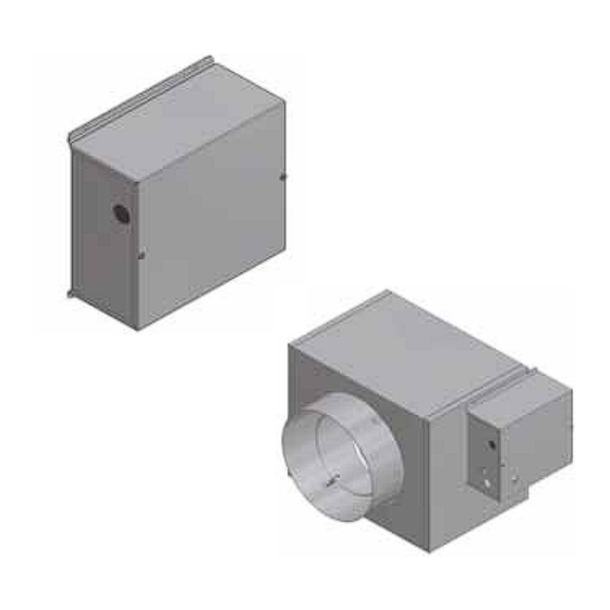
Mount the VV551 controller on the side of the VAV box in a customer-
supplied control box (refer to
Figure
1.).
Note: The following image is intended as an example and does not reflect
an actual customer-supplied control box.
Place it over the damper shaft and secure it to the VAV box.
6
Figure 2.
VV551 wiring diagram
J11, Heat 3
Fan If Applicable
Hot Water 2-
position
J9, Heat 1
ON/OFF Water
Valve,
24 Vac
J8, 24 volt
Fan If Applicable
J11, Heat 3
Hot Water
Proportional
J10, Open
Proportional
Water Valve,
J9, Close
24 Vac
J8, 24 volt
Fan If Applicable
J11, Heat 3
Figure
Electric Heat
Staged/Pulse
J10, Stage 2
Width
Modulation
Heater Stage
Contactors,
(PWM)
J9, Stage 1
24 Vac
J8, 24 volt
3
Figure 1.
Example of a customer-supplied control box
24 Vac Transformer
24 V
24 V
Air Valve Open (Counterclockwise)
Ground
Air Valve Closed (Clockwise)
AC Power Wiring
Actuator Wiring
TOOL
IN OUT
J2-3
J2-2
J2-1
COMM COMM COMM
ZONE GND SET
AUX
GND
Primary Air Temperature (Supply) or
1
.
Dry
Discharge Air Temperature
2
Contacts
3
4
5
Note: Heat 3 represents fans in series or parallel fan powered VAV
boxes or Stage 3 local or remote heat in no fan situations.
Advertisement

Related Manuals for Trane Tracer VV551 VAV


Summary of Contents for Trane Tracer VV551 VAV
- Page 1 • 1.34 lbs. (.61 kg.) with Belimo actuator SAFETY WARNING supplied control • 1.88 lbs. (.85 kg.) with Trane actuator Only qualified personnel should install and service the equipment. The box: installation, starting up, and servicing of heating, ventilating, and air- conditioning equipment can be hazardous and requires specific knowledge and training.
- Page 2 The Tracer VV551 VAV controller communicates with the building automation system and with other controllers over a LonTalk® communication link. Comm5 is the Trane implementation of LonTalk® protocol. For instructions on LonTalk® communication wiring, refer to the Tracer Summit™...
Need help?
Do you have a question about the Tracer VV551 VAV and is the answer not in the manual?
Questions and answers