Table of Contents
Advertisement
Quick Links
Advertisement
Table of Contents

Related Manuals for SATO Argox iX4-350


Summary of Contents for SATO Argox iX4-350
- Page 1 Impressora Argox IX4 Planejada para atender à grandes volumes de impressões, as Impressoras da Linha IX4 tem a capacidade de suportar rolos de etiquetas de 1,5 polegadas à 3 polegadas e fita de ribbon de até 450 metros e 110mm de largura.
- Page 2 iX4 Series Printer User Manual [Installation Video] http://www.argox.com service@argox.com Version: 1.7...
-
Page 3: Liability Disclaimer
iX4 Series Printer User Manual Liability Disclaimer Argox Corporation takes steps to assure that the company’s published engineering specifications and manuals are correct; however, errors do occur. Argox reserves the right to correct any such errors and disclaims any resulting liability. In no event shall Argox or anyone else involved in the creation, production, or delivery of the accompanying product (including hardware and software) be liable for any damages whatsoever (including, without limitation, damages for loss of business profits, business... - Page 4 iX4 Series Printer User Manual This is a Grade A product. In living environment, the product may cause interference to radio communications. In this case, the user is encouraged to try to correct the interference by effective measures. Caution Ensure to connect the power cord of power adapter to a socket-outlet with earth connection.
-
Page 5: Table Of Contents
iX4 Series Printer User Manual Contents Introduction ......................1 Features ....................... 1 Unpacking ....................2 Understand your printer ................3 1.3.1 Perspective view ................3 1.3.2 Back view ..................4 1.3.3 Interior view ................... 6 Printer control panel ................... 7 1.4.1 Status lights .................. - Page 6 iX4 Series Printer User Manual Configuration on Web Setting Tool................70 4.1 Attaching the power cord ................70 4.2 Connecting the printer to a LAN hub ..............70 4.3 Getting the IP address of the printer ..............71 4.4 Logging in to the web setting tool ..............71 Maintenance ......................
-
Page 7: Introduction
1 Introduction Thank you for purchasing an Argox iX4 Series industrial barcode printer. This manual provides information about how to set up and operate your printer, load media, ribbon and solve common problems. Illustrations are provided to help you quickly become familiar with the printer. 1.1 Features ■... -
Page 8: Unpacking
1.2 Unpacking Make sure all of the following items are included in your package. Printer Quick Installation Guide 1” ID Core for Ribbon USB Cable AC Power Cord When you receive the printer, open the package immediately and inspect for shipping damage. -
Page 9: Understand Your Printer
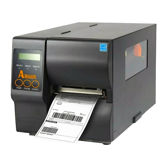
1.3 Understand your printer 1.3.1 Perspective view Top Access Door iX4-250, iX4-350 LCD Display iX4-240, iX4-200 Top Access Door Control panel... -
Page 10: Back View
1.3.2 Back view iX4-240, iX4-250, iX4-350 Standard Ethernet USB Type A USB Type B RS232 Serial Power switch AC power connector iX4-240, iX4-250, iX4-350 Optional WIFI Parallel port GPIO... - Page 11 iX4-200 Standard USB Type B RS232 Serial Power switch AC power connector...
-
Page 12: Interior View
1.3.3 Interior view Internal Parts and Features Ribbon Supply Spindle Ribbon Pick-up Spindle Media Supply Spindle Feed Slot Rotate Head Latch Head latch Thermal Print Head Paper sensor Paper Roller Outside Media Guide... -
Page 13: Printer Control Panel
1.4 Printer control panel There are three lights on the front panel - READY, MEDIA and RIBBON. These indicators display operation status of the printer. Three Buttons – FEED, PAUSE, CANCEL can control printer simple function. 1.4.1 Status lights Status lights help you check printer’s condition. The following tables show the status lights and the conditions they indicate. - Page 14 LCD Display READY MEDIA RIBBON Description CANCEL ... Blinking ON Press CANCEL KEY to interrupt and delete a print task CLEAR FLASH Blinking ON Clear flash memory. CUTTER Blinking ON Cutter has failed, or there is paper FAILED jam inside the cutter. MEMORY FULL Blinking ON Printer buffer is full caused by the loaded soft fonts, graphics or...
-
Page 15: Buttons
LCD Display READY MEDIA RIBBON Description CALIBRATION . Blinking Blinking Press PAUSE KEY + POWER ON to calibrate media. MEDIA OUT Blinking Blinking Media is not installed or used up. Printer fails to detect the media gap. The media sensor is out of range during calibration. -
Page 16: Get Started
2 Get started This chapter describes how to set up your printer. 2.1 Attach the power cord 1. Make sure the power switch is set to the OFF position. 2. Place the printer within cable distance of the host and printer (USB or Serial cable.) 3. -
Page 17: Turn On/Off Your Printer
2.2 Turn on/off your printer When your printer is connected to a host (a computer), it is good to turn on the printer before turning on the host, and turn off the host before turning off the printer. 2.2.1 Turn on your printer 1. -
Page 18: Turn Off Your Printer
2.2.2 Turn off your printer 1. Make sure READY、MEDIA、RIBBON are solid blue before turning off the printer. 2. To turn off your printer, turn off the Power Switch as below. The “O” is the OFF position. Caution Do not turn off your printer during data transmission. -
Page 19: Load Media
2.3 Load media The iX4 Series printers offer three different loading modes: standard, peel-off, or with a cutter. Standard mode allows you to collect each label freely. • Peel-off mode peels backing material away from the label as it prints. After •... -
Page 20: Prepare Media
2.3.1 Prepare media The inside wound and outside wound media roll can be loaded into the printer the same way. In case the media roll is dirty during shipping, handling or storage, remove the outside length of the media. It helps avoid dragging adhesive and dirty media between the printhead and platen roller. -
Page 21: Placing Media Roll
2.3.2 Placing media roll Load Media In Standard Mode Lift the top cover to expose the media compartment. Door Insert the media roll into the media supply spindle and move the media guide to the inside. Media Guide Media Supply Spindle... - Page 22 Turn the head latch counter-clockwise and open the outside media guide counter-clockwise for media insert. Head Latch Outside Media Guide 4. Label must face up when lead the media through the print head module. Media is under “media guide” and through two rings before lock “Outside Media Guide”. Then, under the paper sensor guide module and over the roller.
- Page 23 5. Return the outside media guide and hook the head latch. Head Latch Outside Media Guide 6. Close the top cover.
- Page 24 7. Press the FEED button if the printer is already on. Important After the media is loaded, please perform media calibration to calibrate the label sensor before printing. Make sure the die-cut media’s label length is at least 25mm or Note longer, for direct thermal printing in tear-off mode with perforation.
-
Page 25: Load Media In Peel Off Mode
Load Media In Peel Off Mode Steps 1 to 3 are the similar with “Standard Mode”. 1. Lift the top cover to expose the media compartment. 2. Insert the media roll into the media supply spindle and move the media guide to the inside. - Page 26 Push down the peel-off mechanism release lever and lead the media backing paper behind the dispenser (peeler) module. Media Peel Lever Close the dispenser (peeler) module using the peel-off mechanism release lever. Return the outside media guide and hook the head latch. Head latch Outside media guide (Dispenser) peeler lever...
- Page 27 Close the top cover and turn on the printer or press the FEED button if the printer is already on. Important After the media is loaded, please perform media calibration to calibrate the label sensor before printing.
- Page 28 Load Media In Rotary Cutter Mode Steps 1 to 3 are the similar with “Standard Mode”. Lift the top cover to expose the media compartment. Insert the media roll into the media supply spindle and move the media guide to the inside.
- Page 29 Return the outside media guide and hook the head latch. Head Latch Outside Media Guide Close the top cover and turn on the printer or press the FEED button if the printer is already on. The printer will then feed the labels through the cutter automatically.
- Page 30 Load Media In Guillotine Cutter Mode Steps 1 to 3 are the similar with “Standard Mode”. Lift the top cover to expose the media compartment. Insert the media roll into the media supply spindle and move the media guide to the inside.
- Page 31 Push back Guillotine Cutter and return the outside media guide and hook the head latch. Head Latch Outside Media Guide Close the top cover and turn on the printer or press the FEED button if the printer is already on. The printer will then feed the labels through the cutter automatically.
-
Page 32: Media Types
2.3.3 Media types Your printer supports various media types, including non-continuous media, continuous media, and fanfold media. The following table provides details about them. Media Type Looks Like Description Non-Continuous Non-continuous media is the typical media for Media bar code printing. Labels and tags are made of various materials, such as paper, fabric or cardstock, and are separated by gaps, holes, notches or black marks. - Page 33 Media Type Looks Like Description Continuous Continuous media does not have gaps, holes, Media notches or black marks. It allows you to print data anywhere on the media. A cutter may be used for splitting labels. Mostly it is used for direct thermal printing.
-
Page 34: Load Ribbon
2.4 Load Ribbon The following steps only apply to thermal transfer printing mode. Direct thermal does not need ribbon to be installed. iX4 Series printers apply to both Inside wound ribbon and Outside wound ribbon. Printers can switch automatically. Note Media and ribbon types should be matched to provide with optimal print results. -
Page 35: Placing Ribbon Roll
2.4.1 Placing Ribbon Roll 1. Lift the top cover to expose the media compartment. 2. Turn the head latch counter-clockwise. Head latch... - Page 36 3. Unwrap the ribbon and separate the ribbon roll from the bare core. Insert the ribbon roll onto the ribbon supply spindle. Ribbon Supply Spindle 4. Lead the ribbon through the print head module. Attach the edge of the ribbon onto the bare core and wind it a bit onto the core. Make sure the coating side of the ribbon is face down.
- Page 37 5. Insert the core onto the ribbon pick-up spindle. Turn the pick-up spindle to ensure the ribbon is tightly wound. Ribbon Pick-up spindle 6. Close the top cover and turn on the printer.
-
Page 38: Printer Operation
3 Printer operation This chapter provides more specific information about printer operation. 3.1 Front Panel Change settings via buttons on panel: Buttons Function PAUSE+CANCEL Press to enter setting mode. Press again to exit setting mode and return to normal mode. FEED Press to show next parameter. -
Page 39: Lcd Function Setting Procedure
3.1.1 LCD Function Setting Procedure The following procedure is an example of setting procedure to direct thermal printing mode: READY (203, AUTO) Press both PAUSE + CANCEL buttons. Then release the buttons to enter settings. PRINT MODE Function which has “*” THERM. - Page 40 Press over 5 seconds to set different languages. PAUSE + CANCEL Item Range Factory Default LANGUAGE ENGLISH, ENGLISH FRENCH, GERMAN, ITALIAN, SPANISH, PORTUGUESE, Press less then 1 second to set printer function. PAUSE + CANCEL Factory Item Range Remarks Default THERM.
- Page 41 TPH VER OFFSET -009~009 mm 000 mm To adjust offset of vertical print position. RECOVER ENABLE, Will not reprint after recovering from ENABLE media-out or ribbon-out errors. PRINT DISABLE CUTTER (Restart printer after change setting) INSTALLED PEELER INSTALLED Available only in PPLB printer language. STANDLONE FORM FONT (Restart printer after change setting)
- Page 42 2400/ 4800 Should be as same as setting of host. 9600 / 19200 / BAUD RATE 9600 38400 / 57600 / (Restart printer after change setting) 115200 NONE Should be as same as setting of host. PARITY (RS232) NONE (Restart printer after change setting) EVEN 8 DATA BITS Should be as same as setting of host.
- Page 43 LAST SAVED: NO.1~15, NO.17, NO.22, NO.24~25 and language will be loaded. LAST SAVED FACTORY: LAST SAVED LOAD DEFAULTS FACTORY NO.1, NO6, NO9, NO11, NO14~15, NO17, NO.27~30 will be loaded. NETWORK NETWORK: NO.27~30 will be loaded. (Restart printer after change setting)
- Page 44 Ethernet settings and parameters Item Range Factory Default Remarks DHCP DISABLE If printer has been connected to a router, IP address will be assigned automatically by DHCP server after power on. ENABLE If printer is not connected to a router, with DHCP disabled, settings of IP ADDRESS, SUBNET MASK, and DEFAULT GATEWAY settings will be available on LCD.
- Page 45 To have more information on Ethernet settings, please refer to Ethernet User’s Guide. WiFi module (Option) Item Range Remarks WIFI SSID Read only WIFI module is an option for iX4 Series. Connect printer to WIFI IP PC and use print tool to set WIFI module. To have more Read only ADDRESS information, please refer to Print Tool user guide.
-
Page 46: Printing Media Calibration & Configuration
Printing Media Calibration & Configuration Before calibration, be sure media and ribbon (for thermal transfer printing) have been loaded correctly. The label sensor needs to locate properly to index labels’ gaps/ notches/ holes. After the media is loaded, please perform media calibration to calibrate the label sensor in advance. -
Page 47: Printing A Configuration Report
3.3 Printing a Configuration Report To perform a self-test and print a configuration report, helping to check printer’s print quality and internal settings. Steps as below: 1. Turn off the printer. 2. Load media and ribbon. 3. Press and hold the FEED button while turning on the power. 4. - Page 48 Sample of Configuration Report...
- Page 49 1. Version Information The firmware version and its build date. 2. Standard RAM Total SDRAM size. 3. Available RAM RAM is able to be used. 4. Flash Type The flash memory type and size. 5. Available Flash Flash is able to be used. 6.
- Page 50 16. Speed The speed of printing. The unit is inch per second (ips). 17. Darkness The current darkness. 18. Print Method It is either thermal transfer (TT) or direct thermal (DT) printing. TT requires ribbons and DT doesn't. 19. Print Length The total print length.
- Page 51 26. Cutter Enabled/Disabled Enable or disable the cutter during the printing process. 27. Dispenser (Peeler) Enabled/Disabled Enable or disable the dispenser (peeler) during the printing process. 28. Cutter/Dispenser (Peeler) Offset Move the cutting line or the peeling position forward or backward. The value in the angle brackets is the offset unit.
- Page 52 40. IPv6 Type It is the IPv6 address type of your printer. There are four types: NONE, NORMAL, EUI and ANY. 41. IPv6 Address The static IPv6 address of your printer. 42. Link Local The IPv6 address that used in a network segment. It is allocated automatically.
- Page 53 If your printer has a Wi-Fi module, your PPLB configuration label will contain the following entries: 1. FW Version WLAN board firmware version. 2. Date WLAN board firmware version date. 3. IP Address The IP address of your printer. When DHCP is enabled, it shows the automatically assigned IP address;...
- Page 54 10. SSID Short for service set identifier. It is the name of a wireless local area network. 11. Mode There are ad-hoc and infrastructure mode. Refer to Print Tool Network type description from Technical manual. 12. Country Code The country or region. 13.
- Page 55 PPLA...
- Page 56 PPLZ...
-
Page 57: Resetting To Factory Default Settings
Resetting to Factory Default Settings Be cautioned that this will reset all printer settings back to defaults; if possible, print the configuration label in advance before reset. All settings stored in FLASH memory are retained even after turning off the printer. Printer mode without LCD can see indicators. -
Page 58: Media Sensing
3.5 Media sensing Printer offer two types of media sensor: transmissive and reflective. They are used for detecting specific media types. Both sensor types are installed together as a movable module. 3.5.1 Transmissive sensor The transmissive sensor is used for detecting gaps across the entire width of the label. -
Page 59: Reflective Sensor
3.5.2 Reflective sensor The reflective sensor detects gaps, notches and black marks. Multi Columns Notch Black Mark Flip the media so the black-mark side is facing down to align with the sensor. -
Page 60: Adjust Position Of Label Sensor
3.5.3 Adjust Position of Label Sensor Function of the label sensor is to detect the gap, notch, or holes of labels, to help the printer for accurate print positions and label length. For labels with gaps, label sensor can be positioned wherever media locates. If labels with notches or holes are in use, pull in or out Paper Sensor Position Lever, to horizontally adjust position of label sensor Paper Sensor Position Lever... -
Page 61: Communications
3.6 Communications 3.6.1 Interfaces and Requirements This printer comes with USB type A and type B interface, a nine-pin Electronics Industries Association (EIA) RS-232 serial data interface, a standard Centronics parallel interface(Option), GPIO interface(Option), . USB Interface Requirements The Universal Serial Bus (USB) interface is compatible with your existing PC hardware. The USB’s “plug and play”... -
Page 62: General-Purpose Input/Output (Gpio)
General-purpose input/output (GPIO) Pins depend on usage and the signal is user selectable. The function is diversity. For general-purpose, I/O signals programmed as inputs can cause CPU interrupted. For more information, contact local dealer. Ethernet Module Status Indicators The indicators with two different colors help users understand the status of Ethernet: Description Status... -
Page 63: Driver Installation
3.7 Driver installation The bundled printer driver can be applied to all applications under Windows XP/ Vista/ Windows 7/ Windows 8/ Windows 10, supporting 32-bit/ 64-bit operation systems. With this driver you can operate any popular Windows software applications including Argox Bartender UL label editing software or MS Word, etc., to print to this printer. -
Page 64: Installing A Plug And Play Printer Driver (For Usb Only)
3.7.1 Installing a Plug and Play printer driver (for USB only) Note: We strongly recommend that you use the Seagull Driver Wizard instead of the Microsoft Windows Add Printer Wizard when installing and updating your Drivers by Seagull. (Even though the "Add Printer Wizard" is from Microsoft, it too easily performs a number of tasks incorrectly when updating existing drivers. - Page 65 3. Run the driver from Argox website. On the prompt, Windows Printer Driver, select “I accept…” and click "Next". 4. Assign the directory to keep Seagull driver, (for example: C:\Seagull) and click "Next".
- Page 66 5. Click "Finish". 6. Select Install printer drivers and Click "Next"...
- Page 67 7. On the Seagull Driver Wizard prompt, select the first radio button to “Install a driver for a Plug and Play printer” Then click “Next.” 8. Enter Printer name (i.e. Argox iX4-250 PPLB) and select "do not share this printer”, and click "Next"...
- Page 68 9. Check all the data on the showing screen, if it is correct, click "Finish". 10. After the related files have been copied to your system, click "Finish".
- Page 69 11. After driver installation is complete, click "Close". The driver should now be installed.
-
Page 70: Installing A Printer Driver (For Other Interfaces Except Usb)
3.7.2 Installing a Printer Driver (for other interfaces except USB) 1. Turn off the printer. Plug the power cable into the power socket on the wall, and then connect the other end of the cable to printer's power socket. Connect the Parallel cable, Serial cable, or Ethernet cable to the proper port on the printer and on your computer. - Page 71 3. Assign the directory to keep Seagull driver, (for example: C:\Seagull) and click "Next". 4. Click "Finish".
- Page 72 5. Select Install printer drivers and Click "Next" 6. Make sure printer is connected to PC, select “Other” and click “Next”:...
- Page 73 7. Select model & emulation - the following examples are based on model iX4-250 PPLB: 8. Select the port of the printer and click "Next".
- Page 74 9. Enter Printer name (i.e. Argox iX4-250 PPLB) and select "do not share this printer”, and click "Next". 10. Check all the data on the showing screen, if it is correct, click "Finish".
- Page 75 11. After the related files have been copied to your system, click "Finish". 12. After driver installation is complete, click "Close". The driver should now be installed.
-
Page 76: Configuration On Web Setting Tool
4 Configuration on Web Setting Tool Before doing settings for your printer, be sure that you have a LAN cable. The cable is connected to the LAN connector of your printer. The LAN connector is an 8-PIN RJ45 type modular connector. Please use the LAN cable of CAT 5 of a proper length to connect the LAN connector on the printer to a LAN hub as appropriate. -
Page 77: Getting The Ip Address Of The Printer
4.3 Getting the IP address of the printer You can have the printer run a self test to print a configuration label, which helps you get the IP address of your printer connected to the LAN hub. 1. Turn off the printer. 2. - Page 78 When the connection is successful, the Login page will be displayed. Input the user name and password to log in to the web setting tool. The default user name and the default password are given below: Default user name: admin Default password: admin The default password can be changed in the "Device Setting \ Change Login Password"...
-
Page 79: Maintenance
5 Maintenance Vertical streaks in the printout usually indicate a dirty or faulty print head. (Refer to the following examples.) Clean the print head. If the problem persists, replace the print head. For unstable ribbon roll rotation, check the label path and make sure the head latch is securely closed. -
Page 80: Cleaning
5.1 Cleaning To maintain print quality and prolong the printer’s life, you need to perform some routine maintenance. Daily maintenance should be done for high volume printing, and weekly for low volume printing. Warning Always turn off the printer before cleaning. 5.1.1 Printhead It is essential to keep printhead clean if you want the best print quality. -
Page 81: Platen Roller
5.1.2 Platen Roller The platen roller is also important for print quality. Dirty platen roller may damage the printhead. Clean the platen roller right away if the adhesive, dirt or dust accumulates on it. 1. Moisten a soft cloth with absolute ethyl alcohol. 2. -
Page 82: Printer Adjustments
5.2 Printer Adjustments 5.2.1 Printer Head Pressure Adjustment Note The printer head pressure adjustment is available to iX4 series model which is with the serial number of 21C58061 or former. You can also contact your local service center or printer supplier for technical support. -
Page 83: Ribbon Tension Adjustment
Step.2 Move the pad horizontally. Position 1 is thicker than position 2. If you want more pressure, move pad to position 1. Screw in position 2 (- pressure) Screws in position 1(+ pressure) 5.2.2 Ribbon Tension Adjustment Both ribbon supply spindle and ribbon pickup spindle are equipped with control knobs to adjust ribbon tension. - Page 84 Too much tension at ribbon supply may result in ribbon not moving smoothly. Once it happens, rotate counter-clockwise control knob of ribbon supply, to reduce ribbon tension to balance the tension. ⚫ Rotate control knob counter-clockwise to reduce ribbon tension. [Remark]: The ribbon shaft has its user-friendly feature to allow users to adjust the tension of ribbon shaft by rotating the knob.
-
Page 85: Printing Wrinkle Adjustment
5.2.3 Printing Wrinkle Adjustment During printing, ribbon may wrinkle and cause abnormal printing quality. The following describes how to solve ribbon wrinkle accordingly. Once the printouts as above appear, the possible cause may be the unequal positions of Ribbon Bracket, which needs to be adjusted properly to make its heights equally the same at both sides. - Page 86 3. Print a test page to check print quality. If the quality is improved, stop the adjustment; if not, continue with next step. 4. If the test print appears as below, remain the screw at the right of Ribbon Bracket fixed, then loose the screw at the left, and gradually fine-tune upward, until the print quality gets improved.
-
Page 87: Rtc Battery Replacement
5.3 RTC Battery Replacement RTC stands for real-time clock. It is a battery powered clock that keep track of the current date and time. If your printer has a built-in RTC, you’ll find the RTC battery on the main board. The RTC battery keeps the RTC running even if the printer is turned off. -
Page 88: Troubleshooting
6 Troubleshooting This chapter provides the information about printer problems and solutions. 6.1 Printer issues The printer won’t turn on ■ Did you attach the AC power cord? ■ Check the power connection from the wall socket to the printer. Test the power cord and the socket with other electrical devices. -
Page 89: Media Issues
6.2 Media issues The media is out ■ Load a new media roll. The paper is jammed ■ Open the printer and clear the jammed paper. ■ Make sure the paper is held properly by the Media Guides. The printing position is not correct ■... -
Page 90: Ribbon Issues
6.3 Ribbon issues The ribbon is out ■ Load a new ribbon roll. The ribbon is broken ■ Check the print darkness and adjust it if it is too high, and take the following steps to fix the broken ribbon: Unload the ribbon supply roll and take-up roll from the printer. -
Page 91: Other Issues
6.4 Other issues There are broken lines in the printed label ■ The printhead is dirty. Clean the printhead. The printhead temperature is extremely high ■ The printhead temperature is controlled by the printer. If it is extremely high, the printer will stop printing automatically, until the printhead is cool down. -
Page 92: Specifications
7 Specifications This chapter provides specifications for the printer. 7.1 Printer Model iX4-200 iX4-240 iX4-250 iX4-350 Print method Direct Thermal & Thermal Transfer 300 dpi (12 Resolution 203 dpi (8 dots/mm) dots/mm) Standard: Continuous mode, Tear-off mode Operation Mode Optional: Cutter mode, Dispenser (Peeler) mode Media Reflective sensor x 1 (movable) &... - Page 93 Model iX4-200 iX4-240 iX4-250 iX4-350 CPU Type 32 bit RISC microprocessor Windows Driver (Windows XP/Vista/ Win 7/ Win 8/ Software---Label editing Win 10), BarTender® from Seagull Scientific Software--- Utility Printer Tool Agency Listing CE, FCC, CB/LVD, cULus, ICES, Energy Star Note Print quality and speed is based on 15% print coverage.
-
Page 94: Media & Ribbon
7.2 Media & Ribbon Properties Description Media Size Max. width:4.4” (112mm). Min. width: 1” (25.4 mm). Thickness:0.0025”~0.01” (0.0635mm~0.254mm) 8.26”(210mm) OD on a 3”(76mm) ID core. 7”(177.8mm) OD on a 1.5”(38mm) ID core. Min. width 2.3” (58mm)for partial cutter options. Min. length 1”(25.4mm)for cutter options. Media Type Roll-feed, die-cut, continuous, fan-fold, tags, ticket or plain paper or label. -
Page 95: Electrical And Operating Environment
7.3 Electrical and operating environment Properties Description Power Supply Voltage: AC 100 V ~ 240 V ± 10 % (full range) Frequency: 50 Hz - 60 Hz ± 5 % Temperature Operating: 40F~104F (4C~40C) Storage: -4F~122F (-20C~50C) Humidity Operating: 25 %RH ~ 85 %RH (non-condensing) Storage: 10 %RH ~ 90 %RH (non-condensing) 7.4 Physical dimension Dimension... -
Page 96: Fonts, Barcodes, And Graphics Specification
7.5 Fonts, Barcodes, and Graphics Specification The specifications of fonts, bar codes and graphics depends on the printer emulation. The emulations PPLA, PPLB, and PPLZ are printer programming languages, through which the host can communicate with your printer. Printer Programming Language PPLA Programming Language PPLA 9 fonts with different point size... -
Page 97: Printer Programming Language Pplb
Printer Programming Language PPLB Programming Language PPLB Internal fonts 5 fonts with different point size 8 bits code page : 437, 850, 852, 860, 863, 865, 857, 861, 862, 855, 866, 737, 851, 869, 1252, 1250, 1251, 1253, 1254, 1255 Symbol sets 7 bits code page: USA, BRITISH, GERMAN, (Code pages) -
Page 98: Printer Programming Language Pplz
Printer Programming Language PPLZ Programming Language PPLZ 8 (A~H) fonts with different point size. 8 AGFA fonts: 7 (P~V) fonts with fixed different Internal fonts point size (not scalable). 1 (0) font with scaling point size. USA1, USA2, UK, HOLLAND, DENMARK/NORWAY, SWEDEN/FINLAND, GERMAN, FRANCE1, FRANCE2, ITALY, Symbol sets... -
Page 99: Wireless Lan (Option)
7.6 Wireless LAN (Option) Properties Wireless LAN I/F Hardware Protocol IEEE 802.11 b/g/n Enabled Device WIRELESS PRINTER Operating -20°C ~ +85°C Temperature Destination Europe Frequency 2412 ~ 2462 MHz 2412 ~ 2472 MHz (Center Channel) Channel 1 ~ 11 ch 1 ~ 13 ch Spacing 5 MHz... - Page 100 Properties Wireless LAN I/F 72.2M(Auto-sensing) Antenna External antenna Aerial power 802.11b Max +15 dBm 802.11g Max +17 dBm 802.11n Max +17 dBm Software Connection mode Infrastructure, Adhoc Default IP Address 192.168.1.1 Default Subnet Mask 255.255.0.0 Default ESSID WIRELESS PRINTER Security IEEE 802.11i Cryptograp WEP 128 bit, TKIP (WPA), AES (WPA2)
-
Page 101: Interfaces
7.7 Interfaces This section provides information about IO port specifications for the printer. 7.7.1 USB There are two common USB connectors. Typically, type A is found on hosts and hubs; type B is found on devices. The figure below shows their pinouts. Type A Type B Signal... -
Page 102: Rs-232C
7.7.2 RS-232C The RS-232C on the printer is DB9 female. It transmits data bit by bit in asynchronous start-stop mode. The figure below shows its pinout. Signal Description No Function Transmit Receive No Function Ground No Function Clear to Send Request to Send No Connection Host (DB9) -
Page 103: Centronics
7.7.3 Centronics The 36-pin Centronics on the printer uses parallel communication, and complies with IEEE 1284 compatibility mode (also called SPP, Standard Parallel Port). The figure below shows its pinout. Signal Signal Signal Signal Direction Direction To Printer /STROBE S-GND Signal-GND To Printer Data 1... -
Page 104: Gpio
7.7.4 GPIO The input and output definition is below. Initialize: (1) During initialize process, please set all of output port to high for status clear, it mean all of outputs are active low. (2) The active level maybe customize needed to modify. (3) The input normal state (idle) is high level, so the all of inputs are also active low. -
Page 105: Ethernet
7.7.5 Ethernet The Ethernet uses RJ-45 cable, which is 8P8C (8-Position 8-Contact). The figure below shows its pinout. 1 2 3 4 5 6 7 8 Signal Transmit+ Transmit- Receive+ Reserved Reserved Receive- Reserved Reserved...
Need help?
Do you have a question about the Argox iX4-350 and is the answer not in the manual?
Questions and answers