Hella Gutmann SEG V User Manual
Hide thumbs
Also See for SEG V:
- User manual (1212 pages) ,
- Operating instructions manual (56 pages) ,
- Information sheet (39 pages)
Table of Contents
Advertisement
Quick Links
Advertisement
Table of Contents

Related Manuals for Hella Gutmann SEG V


Summary of Contents for Hella Gutmann SEG V
- Page 1 SEG V User Manual manuals 460 985-23 / 02.22...
- Page 2 US-English..................................
-
Page 3: Table Of Contents
4. Mounting .............................. 20 4.1. Mounting the Rubber Castor ............................20 5. Using the User Manual .......................... 22 5.1. Calling Up the SEG V User Manual ..........................22 6. Installation ............................23 6.1. Charging the Battery..............................23 6.2. Switching On the Device ............................. 23 6.3. - Page 4 7.5. Configuring users................................ 32 7.5.1. Entering the User Name ..........................32 7.6. Installing Password Protection ..........................32 7.7. Configuring the SEG V..............................33 7.7.1. Setting the Display Brightness ........................33 7.7.2. Automatic display dimming ........................... 33 7.7.3. Automatic switching off when inactive ......................34 7.7.4.
- Page 5 Hella Gutmann Table of Contents 8.2. Preparing headlight test ............................. 40 8.2.1. Requirements for Vehicle Setup Area and SEG V..................40 8.2.2. Setup Area for Stationary SEG V ........................41 8.2.3. Vehicle Test ..............................43 8.2.4. Setting Dimensions and Tolerances......................44 8.3.
- Page 6 Table of Contents Hella Gutmann 9.5. Disposal ..................................71 9.6. Technical data................................72 9.7. Declaration of conformity SEG V ..........................74 9.8. FCC Compliance Statement ............................75 SEG V...
-
Page 7: About These Instructions
Text parts marked in this way indicate a possibly dangerous situation, which may lead to death or se- vere injuries if not avoided. CAUTION! Text parts marked in this way indicate a possibly dangerous situation, which may lead to minor or slight injuries if not avoided. SEG V... - Page 8 This marking indicates that the product must not be discarded as domestic waste. The bar underneath the waste bin indicates whether the product was "placed on the market" after 13 August 2005. Refer to manual This marking indicates that the user manual must always be read and always be available. SEG V...
-
Page 9: User Information
2.1.2. Safety Precautions for the SEG V In order to avoid incorrect handling and injury to the user or destruction of the SEG V arising from this, pay attention to the following: •... -
Page 10: Safety Notes Regarding High Voltage/Mains Voltage
• Protect the product from strong impacts and do not drop it. • Do not open the device on your own. Only technicians authorized by Hella Gutmann are allowed to open the device. Warranty and guarantee will be rendered void at any case of unauthorized tampering of the device or if the protective seal is damaged. -
Page 11: Safety Precautions - Risk Of Injury
• Only use the laser in connection with the mounted protective shields. • Replace defective protective shields instantly. • Do not direct the laser beam towards persons, doors or windows. • Never look directly into the laser beam. • Only use the laser sight for the intended purpose. SEG V... - Page 12 700 nm fulfil the conditions of laser class 1. The eye is protected by the eyelid if a user should accidentally, briefly look into the laser beam. Due to the class 2 rating of the laser sight the nomination of a laser protection officer is not nec- essary. SEG V...
-
Page 13: Product Description
Hella Gutmann Product Description | 3. 3. Product Description 3.1. Delivery Contents Count Name SEG V (without 3rd rubber castor) 3rd rubber caster (assembly neces- sary) Retaining clip (for assembly of the 3rd rubber castor) Washer (for assembly of the 3rd... -
Page 14: Checking Delivery Contents
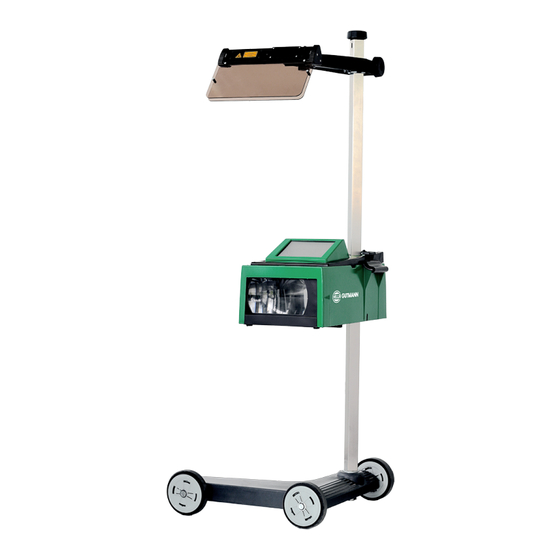
The SEG V is a mobile device for testing the modern headlight systems of motor vehicles. The SEG V is equipped with a modern camera system. This enables precise testing of halogen, xenon, LED and laser headlight systems with the various light distribution functions such as dipped, high beam and fog light but also the vertical light-dark boundary. -
Page 15: Equipment Overview
4 Recessed grip (Adjust the height of the optic hous- the eye of the user from the laser beam.) ing with the recessed grip.) 5 Device base (The device base of the SEG V has rub- 6 Power supply socket (The power supply socket ber castors.) supplies the device with power and charges the in- ternal battery.) -
Page 16: Adjusting The Height Of The Optic Housing
1. Hold both handles (4 + 14) on the optical housing (8). 2. Press the control lever (13). 3. Set the desired height. 4. Release the control lever. ð The optical housing latches in. 3.5. Turning the Optic Housing To rotate the optical housing, proceed as follows: SEG V... -
Page 17: Switching On The Laser
After switching on the laser, the laser output is activated for approx. 30 s via an integrated interval timer. Within this time you can align the SEG V in front of the vehicle. Proceed as follows to switch on the laser module: 1. -
Page 18: Operating The Device
Perform the following functions: • Start the selected function. • Confirm the present entry. • Confirm your menu selection. Cancel Cancel the following functions: • Active function • Input Start Start a function or procedure. Delete Delete data or entries. SEG V... - Page 19 Navigate with the cursor in menus or functions. Virtual keypad Open the virtual keypad for text input. Information Information on the contents of the respective menu can be displayed here. Drop-down list A drop-down list can be opened here. SEG V...
-
Page 20: Mounting
4. Mounting 4.1. Mounting the Rubber Castor The SEG V is entirely assembled except the 3rd rubber castor at the device's base. The delivery contents of the rubber cas- tor include 3 washers and 2 retaining clips. Proceed as follows to mount the 3rd rubber castor to the device base: 1. - Page 21 Hella Gutmann Mounting | 4. 4. Use the second retaining clip to secure the rubber castor. ð Now the 3rd rubber castor is mounted to the SEG V. SEG V...
-
Page 22: Using The User Manual
5.1. Calling Up the SEG V User Manual Proceed as follows to call up the operating instructions for the SEG V via the supplied HGS data carrier: 1. Switch on the PC. 2. Insert the supplied HGS data carrier into a USB port on the PC. -
Page 23: Installation
Prior to putting the device into operation, charge the integrated battery for at least 3 to 4 h. Then charge the integrated battery regularly, e.g. overnight. NOTICE In order to ensure proper operation, we recommend charging the SEG V daily (preferably overnight). Proceed as follows to charge the battery: 1. Connect the power supply plug into the device's socket. -
Page 24: Switching Off The Device
ð Now you can start working with the device. 6.3. Switching Off the Device Proceed as follows to switch off the device: 1. Switch off the device with 2. Observe the confirmation prompt. 3. Confirm the confirmation prompt with . Abort the procedure with SEG V... -
Page 25: Device Configuration
If >Determine automatically (DHCP)< (recommended) is selected, the DHCP server of the network will assign an IP address to the SEG V automatically. This option is set ex works. If >Manual< is selected, then go to SEG V – IP address and enter a free IP network address, e.g.: Network mask 192.168.246.002 / Standard gateway: 192.168.204.2. -
Page 26: Reset Wi-Fi Configuration
2. Use for the function Test Wi-Fi configuration. The Wi-Fi configuration is tested. ð The address of the selected Wi-Fi is displayed under SEG V IP address if the Wi-Fi configuration has been tested suc- cessfully. 7.1.3. Reset Wi-Fi configuration Reset the Wi-Fi configuration again here. -
Page 27: Activate The Screen Duplication
7.1.5. Activate the Screen Duplication The screen duplication enables to have the SEG V display indicated on an external terminal device via VNC viewer. Thus it is possible to do all work steps via external device. The response time of the screen indication depends on the network uti- lization. - Page 28 The use of the software requires merely 5 steps: 1. Download and install the network manager. 2. Start the network manager and go to Documented text > Start asanetwork and connect with the SEG V. The connected SEG V is indicated under Connected services.
-
Page 29: Entering Vehicle Data
Candela (send size) is the light intensity and describes the luminous flux, that is emitted from a light source in a specific direction. ð The selection will be saved automatically. 7.3. Setting the Country Configure the following data here: SEG V... -
Page 30: Setting The Country
5. Observe the information window. 6. Confirm the information window with . Abort the procedure with The language setting is saved automatically. The device switches off and on again automatically. ð The main menu is displayed in the language selected. SEG V... -
Page 31: Setting The Date Format
Proceed as follows to set the time: 1. Select Settings > Device > Region in the main menu. 2. Open the settings window under Time with 3. Set the desired hour under Hour with 4. Repeat step 3 for Minute and Second. SEG V... -
Page 32: Setting Company Data
The introduction of the General Data Protection Regulation (GDPR) of the European Union which came into force on 25 May 2018 includes the requirement to ensure better protection for customer-related data in devices. To prevent access to our diagnostic devices by third parties, we have integrated the function Password protection. SEG V... -
Page 33: Configuring The Seg V
If the device no longer has a valid password, it can only be reactivated with the menu >Starting the factory reset< or with the help of the Hella Gutmann's Technical Help Line. In this case personal data and the Car History will be cleared, and it might not be possible to restore them again. -
Page 34: Automatic Switching Off When Inactive
2. Open the list under Automatic display dimming in case of inactivity with 3. Select >On< or >Off<. The SEG V will switch off automatically after 30 minutes if >On< is selected. ð The selection will be saved automatically. 7.7.4. Calibrate touch screen Proceed as follows to calibrate the touch screen: 1. -
Page 35: Report
7.7.8. Level compensation Activate the level compensation and make settings here. A level sensor registers the inclination angle of the SEG V and compensates floor unevenness and inclinations of up to 2% to prevent improper measurements. 7.7.8.1. Executing Manual Level Compensation Proceed as follows to perform the manual level compensation: 1. -
Page 36: Start Factory Reset
3. Open the list under Level compensation with . 4. Select >Automatic<. If >Automatic< is selected, the level of the vertical and horizontal axis adjusts automatically so that any unevenness in the SEG V setup area is compensated. Now the device is balanced. 5. Confirm the selection with . -
Page 37: Updating The Device
• Hardware version • Device number Hella Gutmann Solutions supplies customers with software updates at varying intervals. These updates contain techni- cal modifications and improvements. We recommend keeping your device up to date with these updates. 7.8.1. Preconditions for an Update Ensure the following to perform updates: •... -
Page 38: Working With The Device
The WLAN symbol is indicated if an active WLAN connection is existing. Language selection Click the symbol to change the user language. Screen duplication This symbol indicates that the screen duplication is activated. 8.1.2. Symbols in the Main Menu Symbols Meaning Home Return directly to the main menu. SEG V... -
Page 39: Headlight Test Symbols
Here people in the dark are detected from a distance and lit in a targeted way. Create vehicle entry manually Here you can create a vehicle by entering vehicle data manually. Asanetwork Retrieve jobs from the Asanetwork controller here. SEG V... - Page 40 Here the device indicates which headlight is tested. 8.2. Preparing headlight test 8.2.1. Requirements for Vehicle Setup Area and SEG V NOTICE In general the requirements on the set-up areas shall correspond to the prevailing laws demands of the pre- vailing countries.
- Page 41 • The dimensions for the set-up area for vehicles as well as the SEG V must correspond to fig. 1. The unevenness of the set-up area for the SEG V must be max. ± 1 mm/1 m. The tolerances of the set-up area for vehicles are specified as in fig.
- Page 42 Name Height difference +/– 1 mm Height difference +/– 1 mm Fig. 4: Name Spacer plate Rail joint without lateral displacement Rolled section not greater than 1 mm • The SEG V is also suitable for fixed installation. SEG V...
-
Page 43: Vehicle Test
Working with the Device | 8. • Rails are mounted onto the ground. • When used as a rail unit, you need to order a rail set for each SEG V (ord. no. 9XS 861 736-001). The rail serves as a drill template during assembly. - Page 44 Depending on the manufacturer, various function tests must be carried out here. • A diagnostic device, e.g. from Hella Gutmann, is required to apply settings for various vehicles with automatic head- light leveling. The vehicle ECU must be in basic mode during the setting process. If the light-dark border is set cor- rectly, then this value is stored as the new normal position.
- Page 45 0.3 on the setting dimension applicable to the vehicle (e.g. for a setting dimension of 1.2 on the vehicle, the correction of 0.3 means that the tolerances of +/- 0.5 are applied with reference to the value 1.5). * see chart in section Performing Headlight Test with a 10-meter Panel [} 64] SEG V...
- Page 46 After switching on the laser, the laser output is activated for approx. 30 s via an integrated interval timer. Within this time you can align the SEG V in front of the vehicle. Proceed as follows to switch on the laser module: 1.
- Page 47 Working with the Device | 8. Proceed as follows to align the SEG V to the vehicle: 1. Position the SEG V at a distance between 30 and 70 cm in front of the headlights. 2. Switch on the laser sight.
- Page 48 8.3.3. Adjusting the Height of the Laser Sight The laser sight provides the option to align the SEG V and headlights using a laser pointer. Two parallel points on the vehi- cle front can be detected with the generated light band. If the required power supply (9 V block battery, 9 V type) is not available, then the alignment can be carried out using the broad-band sight.
Need help?
Do you have a question about the SEG V and is the answer not in the manual?
Questions and answers