Table of Contents
Advertisement
Quick Links
Advertisement
Table of Contents

Related Manuals for Datacom DM4370


Summary of Contents for Datacom DM4370
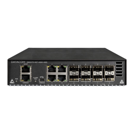
- Page 1 M4370 10G CARRIER ACCESS SWITCH INSTALLATION GUIDE 204.4314.03 – September/2022...
-
Page 2: Legal Note
Legal Note LEGAL NOTE In spite the fact that all the precautions were taken in development of the present document, DATACOM shall not be held responsible for eventual errors or omissions as well as no obligation is assumed due to damages resulting from the use of the information included in this guide. -
Page 3: Contacts
Contacts CONTACTS ECHNICAL UPPORT Datacom has available a support portal - DmSupport, to help the customers in use and config of our equipment. Access to the DmSupport can be made through link: https://supportcenter.datacom.com.br In this site the following are available: firmwares, technical datasheets, config guide, MIBs and manuals for download. -
Page 4: Product Documentation
DM4370 – Installation Guide Product Documentation PRODUCT DOCUMENTATION BOUT THIS OCUMENT This document is part of a set of documents prepared to provide all necessary information about DATACOM products. OFTWARE LATFORM – UICK ONFIGURATION UIDE Provides instructions on how to set the functionalities in a quick manner in the equipment –... -
Page 5: Table Of Contents
ANAGEMENT NTERFACE USB I ) .......................... 12 NTERFACE EVICE ONSOLE ..............................13 NTERFACES ................................15 OWER NPUTS INSTALLING THE DM4370 ..............................17 DM4370 S ........................17 WITCH ACKAGE ONTENTS ............................18 DENTIFYING THE RODUCT ..............................18 REPARING THE ............................ 19... - Page 6 DM4370 – Installation Guide Contents ..........................20 ONNECTING THE OWER UPPLY ’ ........................20 HECKING THE WITCH PERATION INSTALLING AND REMOVING TRANSCEIVERS.......................... 22 SFP/SFP+ M ..........................23 NSTALLING ODULES SFP/SFP+ M ..........................23 EMOVING ODULES LOGGING IN FOR FIRST TIME ..............................25 CONSOLE I ........................
-
Page 7: Introducing The Hardware Installation Guide
BOUT THIS UIDE This manual provides information about hardware specification and installation procedures from DM4370 switch. This document also covers initial configuration, those normally needed after hardware installation. It is assumed that the individual or individuals managing any aspect of this product have basic understanding of Ethernet and Telecommunications networks. - Page 8 DM4370 – Installation Guide Introducing the Hardware Installation Guide WEEE Directive Symbol (Applicable in the European Union and other European countries with separate collection systems).This symbol on the product or its packaging indicates that this product must not be disposed of with other waste.
-
Page 9: Getting Started
DM4370 – Installation Guide Getting Started GETTING STARTED 2.1 S AFETY ARNINGS Before to continue, read carefully the following safety warnings: Prior to installation carefully read the whole manual. Pay attention to the safety instructions during installation, operation or maintenance of this product. -
Page 10: Hardware Specifications
More information on the switch’s capabilities can be found in the Technical Specifications chapter. 3.2 PWR LED (P OWER The PWR LED is an indicator that informs visually the status of the DM4370 power supply. The table below shows the expected behavior for this indicator. Color... -
Page 11: Console Interface
ONSOLE NTERFACE The DM4370 switch has a console interface for the local management of the product. The console interface uses an RJ45 connector and follows the RS232 (EIA/TIA 574) standard. A cable with a male RJ45 connector and a female DB9 connector must be used for the connection to a desktop or laptop. -
Page 12: Thernet Anagement Nterface
Console Interface is accessible via type B mini-USB adapter cable to type A USB host (accessory not included with the switch). The driver to use this interface in Windows can be found on the Datacom website. Contact Technical Support for more information on using this interface. -
Page 13: Data Interfaces
3.7.2 Gigabit Ethernet Interfaces (1000Base-X) The DM4370 has 4 Gigabit Ethernet interfaces in dedicated SFP connectors and numbered from 5 to 8 on the front panel. There are LINK/ACT and SPEED LEDs that are built into the connectors corresponding to each interface, as shown below. - Page 14 3.7.3 SFP+ Gigabit Ethernet Interfaces (10GBase-X) The DM4370 switch has 4 10 Gigabit Ethernet interfaces on dedicated SFP+ connectors and numbered from 1 to 4 on the front panel. There are LINK/ACT and SPEED LEDs that are built into the connectors corresponding to each interface, as shown below.
-
Page 15: Power Inputs
OWER NPUTS The DM4370 switch has two independent power inputs on the rear panel, as shown in figure below. The product is turned on and operates automatically if either input is powered within the specified voltage levels. Figure 8 – DM4370 Rear Panel... - Page 16 The image below shows the DC jack plug polarity information. Figure 10 – DC Jack plug polarity The external 12V power supply is a switch accessory, sold separately. Use only external power supply provided by DATACOM. Consult Technical Support for further information. 204.4314.03 – September/2022...
-
Page 17: Installing The Dm4370
This chapter explains the procedures, recommendations, and attention related to installing the DM4370. The DM4370 must be installed in a dry, ventilated location. The sides, front panel and rear panel must remain unobstructed for proper switch ventilation and air convection. Never support any type of material over the switch. -
Page 18: Identifying The Product
Check that the switch received matches the illustrations in this manual, as shown in figure below. The DM4370 switch has a label on the bottom of its mechanical base. It contains model information, product code and serial number. Check if there is any divergent information on the label in relation to the information present on the packaging. -
Page 19: 19- Inch Rack Installation
Remove the screws securing the front rubber feet of the switch using a Phillips screwdriver, and use the same screws and the same hole to secure the DM4370 switch to the adapter, as shown in the image below. Figure 12 – MA-01 After installing the switch to the adapter, place the assembly on the rack and insert two standard M5 screws (not shipped with the switch) into each side ear of the adapter to secure the assembly to the rack’s cage nuts... -
Page 20: Desktop Installation
Installing the DM4370 4.5 D ESKTOP NSTALLATION The DM4370 switch has tabletop rubber feet, as shown below. Choose a flat surface near to an AC or DC power source to install the switch. Figure 14 – DM4370 bottom view 4.6 C... - Page 21 DM4370 – Installation Guide Installing the DM4370 You should be able to see the fan, positioned at the rear panel, moving after the Step 2 switch is turned on. Table 8 – Operating normally Find further information on the expected LED behavior in Hardware Specifications chapter.
-
Page 22: Installing And Removing Transceivers
This chapter describes how SFP/SFP+ modules should be installed and removed. It also provides information about the DATACOM guidelines for the cleaning and storage of modules and optical fibers. SFP (Small Form-factor Pluggable) and SFP+ modules are inserted into the SFP/SFP+ cages, operating as transceivers between the switch and the selected optical communication path. -
Page 23: Nstalling Sfp/Sfp+ Modules
DM4370 – Installation Guide Installing and Removing Transceivers 5.1 I SFP/SFP+ M NSTALLING ODULES Follow the steps below to install SFP/SFP+ modules to the switch. Step 1 Insert the module into the SFP or SFP+ slot and push it in until it is firmly inserted, as ... - Page 24 DM4370 – Installation Guide Installing and Removing Transceivers Step Description Remove the optical cords Step 1 Lower the bale-clasp latch Step 2 Pull the module by the bale-clasp latch, as shown in the image below. Step 3 Figure 17 –...
-
Page 25: Logging In For First Time
Figure 18 – Serial interface configuration on the computer The DM4370 switch does not support hardware flow control. In the configuration of the Console Interface the hardware flow control should be disabled. On the PC or laptop, start the terminal emulation program. The initial login ... -
Page 26: Default Account
See the Quick Configuration Guide for more information about the switch's management settings. 6.3 D EFAULT CCOUNT One account is configured by default on the DM4370: admin. Account Password Description admin is an account that has admin level privileges. So, it can view and change... -
Page 27: Changing Default Administrator Account Password
DM4370 – Installation Guide Logging in for First Time 6.4 C HANGING EFAULT DMINISTRATOR CCOUNT ASSWORD For security reasons it is highly recommended to modify the default administrator account password. Entering the configuration mode: Step 1 # configure Entering the user mode:... -
Page 28: Technical Specification
DM4370 4GT+4GX+4XS Height 43 mm Width 189 mm Depth 191 mm Net weight 1.3 kg Table 18 – DM4370 physical specifications 7.4 E NVIRONMENTAL NFORMATION DM4370 4GT+4GX+4XS Operating temperature 0°C to 55°C Operating relative humidity 10% to 90%, non-condensed 204.4314.03 – September/2022... - Page 29 0 to 3,000m Storage temperature -20°C to 70°C Table 19 – DM4370 operating conditions For 10G Ports, when the switch is operating at temperatures above 40°C the user must use industrial-grade SFP+ modules. For 1G Ports, when the switch is operating at temperatures above 50°C the user must use industrial-grade SFP modules.
-
Page 30: Standards And Regulations
DM4370 – Installation Guide Standards and Regulations 8 STANDARDS AND REGULATIONS Class Standard Description Directive 2014/30/EU Electromagnetic Compatibility REQUISITOS TÉCNICOS COMPATIBILIDADE Ato 1120 ELETROMAGNÉTICA PARA AVALIAÇÃO DACONFORMIDADE DE PRODUTOS PARA TELECOMUNICAÇÕES Telecommunication network equipment; ElectroMagnetic ETSI EN 300 386 Compatibility (EMC) requirements;...
Need help?
Do you have a question about the DM4370 and is the answer not in the manual?
Questions and answers