
Subscribe to Our Youtube Channel
Related Manuals for Fass 260G


Summary of Contents for Fass 260G
- Page 1 INSTALLATION MANUAL APPLICATION: FA D07 260G (260gph @ 16psi) Cummins 5.9L/6.7L 24 Valve 2005-2009 *1998.5-2004 with In-tank Pump Modification* **2003-2004 must order FP-1001 Fuel Plate**...
- Page 2 Building extremely “High-Quality” fuel products is our business. We concentrate all of our efforts in this arena. No one else is as specialized as FASS in what we do! This is one of the ingre- dients to insure you are running with the “Highest-Quality” fuel system in the world! We have im- plemented very rigorous testing procedures to provide the “Highest Quality”...
- Page 3 Flush and clean all brass fittings and fuel line from debris. Keep debris from entering the internals of the system during installation. Getting debris in the “T” port can lock up the motor. If the motor does lock up from debris call FASS for technical assistance.
- Page 4 4. For best results in accuracy and efficiency (due to training, communication, and our relationship with our dealer network), we recommend an Authorized or ViP FASS Fuel Systems dealer for the installation. They are prepared to install the FASS fuel pumps with the most efficiency. If a situation/problem arises during the installation, they are the most prepared for that situation/problem.
-
Page 5: Installation
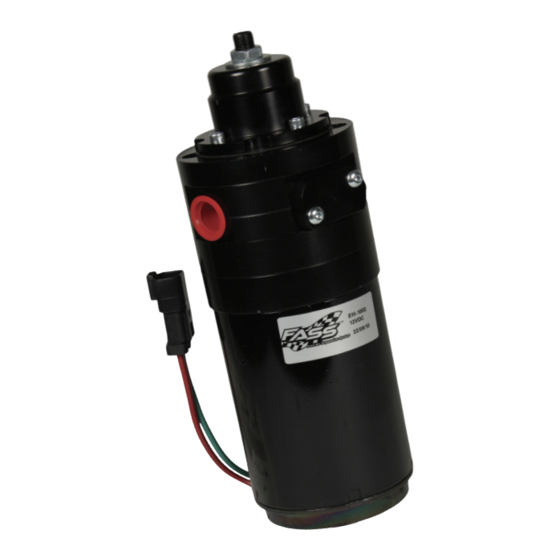
Adjustable Fuel Pump Series 260 GPH 16 PSI (Approximately) A fuel pressure gauge is highly recommended to identify fuel filter life and to prevent engine damage! Adjustment Lock Nut Set screw Boost Compensation Port ‘T’ Fuel Inlet Port “E” To Engine Fuel Pressure Port Installation Step 1:... - Page 6 Contents THB-1001 BHB-1001 FF-3248 MP-9016 *Cable Ties* WH-1004 FL-1002 x14’...
-
Page 7: Mounting Template
Mounting Package Contents BHF-1002 NP-1001 RS-1002 DIPF-1003 PL-2003 10-300 PL-1005 Ring Terminal 1/2” Plug PL-1004 ST-1005Px14” BHN-1001 HC-1001 LW-1001 OR-223 Mounting template 1/4” Lock Washer 1/4” Nut 2 1/4 - 20x3.5” 1/4 - 20x1.75”... - Page 8 The installation of the electrical harness is done first, allowing power to be applied to the pump for lubrication purposes later in the installation. Fuse a. Disconnect the battery before beginning installation. Using ring terminals, Neg. attach red wire of the WH-1004 to the positive battery terminal. The use of corrosion preventative spray is recommended.
- Page 9 Some of the photo’s are of a different application, procedures are the same. Very Important: Before removing the fuel tank, identify “ALL” areas of clear- ance between the tank and bed to install the draw tube assembly. The closer the suction tube is placed to the center of the fuel tank, front to back and left to right, the more usable fuel there will be! Helpful Hints: If more space is required to access the top of the fuel tank, loosen the strap nuts to the end of the stud.
-
Page 10: Very Important
h. Before drilling marked location, clean area of debris. Using the photo double check area selected for any interference including the fuel level arm. i. Drill a 1 1/2” hole, catching all debris. De-bur hole and remove any missed debris in the fuel tank. VERY IMPORTANT: Support fuel tank on both ends allowing the natural for- mation of the tank to take place. - Page 11 Factory harness p. Connect WH-1004 (addressed in Step 1) to the fuel module along with the fac- tory fuel lines q. Connect factory wire harness to the WH-1004. FASS harness r. Reattach filler neck and clamps.
- Page 12 FASS pump. Reconnect the battery. Turn key to the “On” position. With the FASS pump on, squirt a liberal amount of WD-40 or other lubri- cant into the “T” port. This procedure will “wet” the Gerotor and allow for better suction during initial priming.
- Page 13 Do Not use sealant on AN (male flare) fittings. Only use sealant on threads installed into pump assembly. a. Route fuel line to the suction port on the FASS pump labeled “T”. Cut the fuel line. Insert PL-1005 into fuel line using oil. Attach to 10 -300 in ‘T’...
- Page 14 Electrical harness and fuel lines secured and properly tightened? Has the system been primed? 1. Turn key to the ignition position, turning on the FASS pump for 15 sec.. 2. Crank engine and allow to run for at least 1 minute.
- Page 15 Disclaimer: To help insure you receive the proper system and customer support at the local level, FASS has a VIP and Authorized Dealer network representing FASS products. This is one reason you must purchase through a dealer to comply with our warranty policies.
Need help?
Do you have a question about the 260G and is the answer not in the manual?
Questions and answers