Table of Contents
Advertisement
Quick Links
Advertisement
Table of Contents

Subscribe to Our Youtube Channel
Related Manuals for OSEE Mega 15S


Summary of Contents for OSEE Mega 15S
- Page 1 Mega 15S Mega 22S LCD Monitor User Manual...
- Page 3 Product Information Mega 15S/ Mega 22S LCD Monitor Model: Version: V010001 Release Date: May 16th, 2024 Company OSEE TECHNOLOGY LTD. Contact Information No.22 Building, No.68 zone, Beiqing Road, Haidian District, Address: Beijing, China Post Code: 100094 (+86) 010-62434168 Tel: Fax:...
-
Page 4: Contents
The safety matters or operations that user must pay attention to when using this product. Contents The user manual applies to the following device types: ❖ Mega 15S ❖ Mega 22S The images of Mega 15S are adopted in the following descriptions. Before reading the manual, please confirm the device type. -
Page 5: Table Of Contents
Contents Contents ......................I Chapter 1 Overview ..................1 Chapter 2 Safety ..................... 3 Chapter 3 Unpack and Installation ............... 7 Chapter 4 Features ..................10 4.1 Parts and Functions ................10 4.2 Buttons and Functions ..............11 4.3 Joystick Operations ................13 4.4 Power On ................... - Page 6 6.2.1 Add a scene ..................66 6.2.2 Delete a Scene ................67 6.2.3 Add a Tool ..................68 6.2.4 Load/Close Tool Bar ............... 71 6.2.5 Turn ON/OFF a Tool ............... 72 6.2.6 Tool Settings ................... 73 Chapter 7 Scenes and Tools ..........错误!未定义书签。 7.1.2 Delete a Tool ..................
-
Page 7: Chapter 1 Overview
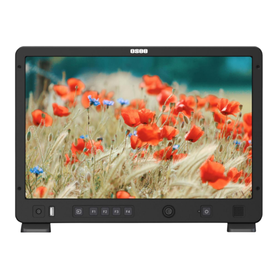
HDMI input and 2Ch 3G/HD/SD-SDI output. It also has a full package of video assisting tools like waveform, vector scope, histogram, zebra, audio meter, focus assist, exposure assist, TC and all kinds of markers. Figure 1 A Diagram of Mega 15S Monitor... - Page 8 Overview Features ◼ Prevailing slim bezel design ◼ Having multi-format input including 4K/3G/HD/SD-SDI and HDMI ◼ Adopting full HD, wide viewing angle TFT glass ◼ Using 10-bit signal processing technology plus advanced conversion technology between the interlacing and the progressive ◼...
-
Page 9: Chapter 2 Safety
Safety Chapter 2 Safety FCC Caution Any Changes or modifications not expressly approved by the party responsible for compliance could void the user's authority to operate the equipment. This device complies with part 15 of the FCC Rules. Operation is subject to the following two conditions: (1) This device may not cause harmful interference, and (2) this device must accept any interference received, including interference that may cause undesired operation. - Page 10 Safety Read, keep and follow all of these instructions for your safety. Heed all warnings. Device Install in accordance with the manufacturer's instructions. Do not beat with a hard object or scratch the LCD display. Do not make the freeze picture displaying on the screen time too long, otherwise, it will leave the afterimage on the screen.
- Page 11 Safety The socket-outlet shall be installed near the equipment and shall be easily accessible. Power Supply Cord Do not defeat the safety purpose of the polarized or grounding-type plug. Do not damage the power cord, place heavy objects on the power cord, stretch the power cord, or bend the power cord.
-
Page 13: Chapter 3 Unpack And Installation
Chapter 3 Unpack and Installation Unpack: When unpacking the components of Mega 15S monitor, please verify that none of the components listed in Table 3.1 are damaged or lack. If there is any missing, contact your distributors or Osee Technology Ltd. for it. - Page 14 Figure 3-1 Stands and Accessories for Mega 15S Battery plate has 2 options: AB or V-mount, figure shows V-mount, D-tap to XLR cable not shown.Cheese plate, battery plate and C-stand adaptor are pre-installed before shipping. Figure 3-2 VESA and Battery Plate(horizontal) Postition for Mega 15S...
- Page 15 Unpack and Installation Please notice that once the HDMI cable lock is inserted into the lock hole, it CAN’T BE REMOVED unless the rear panel is disassembled. Connect required cables for signal input and output. For BNC connections use 75Ω rated connectors. Connect 100~240V50/60Hz AC or 11~17V3A DC battery(with optional battery plate) using the power cord.
-
Page 16: Chapter 4 Features
4.1 Parts and Functions The parts of Mega 15S are shown as below, there are various input and output interfaces for Mega 15S monitor, as shown in Figure 4.1-1 and Figure 4.1-2. Figure 4.1-1 Parts in Rear Panel... -
Page 17: Buttons And Functions
Features Connector Description SDI IN1 SDI input interface SDI IN2 SDI input interface SDI OUT1 SDI output interface SDI OUT2 SDI output interface HDMI input interface, supports HDCP, compatible HDMI IN DVI1.0, HDMI 1.4 CALIBRATE Type-C, used for color calibration BATT IN, External battery NP-F/LP-E6, XLR 3pin Battery Input connector, 11~17V... - Page 18 Features Figure 4.2-1 Buttons in Front Panel Buttons Name Function Choose the input source channel Input Choose the tool assigned to F1 button Choose the tool assigned to F2 button Choose the tool assigned to F3 button Choose the tool assigned to F4 button Joystick Monitor settings, tool settings and Myset operations Power...
-
Page 19: Joystick Operations
Features 4.3 Joystick Operations The monitor provides a Joystick at the front panel, as shown in Figure 4.2-1. It is used for monitor settings, adding tools for scenes, tools settings, zoom image and so on. Use the joystick as a navigation tool to scroll between scenes and set features. The joystick provides multiple functions with five operation directions, Up, Down, Left, Right, Straight Down, and Clockwise Rotation or Counterclockwise Rotation, as shown in Figure 4.3-1. - Page 20 Features Direction Operation In scene tool menu, scroll up to select the previous item. In ZOOM mode, scroll down to exit ZOOM mode. In ZOOM 2X or ZOOM 4X editing mode, scroll down the joystick DOWN to move the starting position of the enlarged image; In monitor settings mode, scroll down to select the next item;...
-
Page 21: Power On
Features 4.4 Power On The power switch is on the right corner of the rear panel of Mega 15S. Use it to power the monitor on or off. It provides one AC power switch to switch on or switch off. As shown in Figure 4.4-1, push the button to the direction “-” to switch on the power, or push the button to the direction “O”... -
Page 22: Input Signal Selection
Features input; At last, press the power button on the front panel, and the power indicator is lit up in highlight orange. It will display the boot screen after power on for 3~4 seconds. After powered on, press the power button for 4s to turn it off. ... - Page 23 Features mode, twice to enter Zoom 4X mode, and scroll down to change from Zoom in to Zoom out. ZOOM 2X ◼ Enter Zoom 2X Mode Scroll right the joystick to access a scene, and then scroll up the joystick to access Zoom 2X mode, the image is enlarged twice as much as the original one.
-
Page 24: Supported Signal Format
Features Figure 4.6-3 Zoom 4X Mode ◼ Zoom 4X Pan Mode After accessing the Zoom 4X Mode, press straight down the joystick to enter Pan mode, scroll left, right, up or down to pan the image, press again to exit Pan mode. - Page 25 Features Table 4.7-1 Supported Signal Format Signal Format HDMI ✓ ✓ 720P24/23.98 ✓ ✓ 720P25 ✓ ✓ 720P30/29.97 ✓ ✓ 720P50 ✓ ✓ 720P60/59.94 ✓ ✓ 1080PSF24/23.98 ✓ ✓ 1080PSF25 ✓ ✓ 1080PSF29.97 ✓ ✓ 1080PSF30 ✓ ✓ 1080I50 ✓ ✓...
- Page 26 Features Signal Format HDMI ✓ 1080P60/59.94 ✓ 2160P24/23.98 ✓ 2160P25 ✓ 2160P30/29.97 ✓ 4KP24/23.98 ✓ 4KP25 ✓ 4KP30/29.97...
-
Page 27: Chapter 5 Menu Operations
Menu Operations Chapter 5 Menu Operations The chapter describes the structure and functionality of the monitor settings, and introduces how to modify and customize the monitor settings. Monitor settings contains the settings as shown in Figure5-1. Figure 5-1 Monitor Settings 5.1 Monitor Settings Checking or modifying the monitor settings with the Joystick Scroll the joystick down to display the menu bar button at the bottom center of the... -
Page 28: Monitor Menu
Menu Operations Figure 5.1-2 Structure of Monitor Settings The menu interface is divided into two parts: First level menu It contains the menu list of the monitor settings, containing Input, Controls, Camera Profiles, System. Scroll up or down to choose an item, the selected one is labeled in highlight orange. -
Page 29: Input
Menu Operations sorts. 5.2.1 INPUT The INPUT menu provides input sources selection, as shown in Table 5.2-1: Figure 5.2-1 Input Menu Table 5.2-1 Description of INPUT Menu Menu Items Default Domain Range Description HDMI: signal from HDMI IN Choose the input signal Input SOURCE HDMI SDI1: signal from SDI IN1... - Page 30 Menu Operations Domain Menu Items Default Description Range Rotate ROTATE 0/180 supported currently) IMAGE Rotate image vertical 0/180 ROTATE direction IMAGE Rotate the image in horizontal OFF/ON MIRROR direction Set the probe before or after LUT loading. This probe will affect the AFTER Probe AFTER...
- Page 31 Menu Operations Set controls→Display Rotate→ Image Rotate item to be 180 or 0, only the input image will reverse vertically, as shown in Figure 5.2-5: Figure 5.2-5 Vertical Rotate ◼ Image mirror Set controls→Display Rotate→ Image MIRROR item to be ON or OFF, only the input image will reverse horizontally, as shown in Figure 5.2-6: Figure 5.2-6 Horizontal Rotate STATUS BAR...
- Page 32 Menu Operations NO SIGNAL: appears if no signal is detected. Normal: the signal format is displayed as HDMI 1080i59.94, etc. when the input is supported by the monitor. ◼ Settings ON: display the input channel, signal format, scene ID and battery indicator (available only when the battery level is 11~17V);...
-
Page 33: Camera Profile
Menu Operations Range of battery level Illustration Powered by AC For the differentiation of battery providers, the illustrations and values for various battery levels in the above table are for reference only, please don't take it for granted and judge it as the real battery level! 5.2.3 CAMERA PROFILE The CAMERA PROFILE menu items are used to set the Input Range, Input Matrix, Signal Format, Color Management and Load User LUT, the menu items are as shown... - Page 34 Menu Operations Menu Items Default Domain Range Description 444 YCBCR 12BIT, 444 RGB 10BIT, 444 RGB 12BIT, 444 XYZ 10BIT, 444 XYZ 12BIT Enable/disable LOG/HDR LOG/HDR ON/OFF function EBU/DCI/ Choose a color profile, ARRI/BMD/ Color COLOR refer to Table 5.2-4 for the Canon/FUJI/ Manage PROFILE...
- Page 35 Menu Operations Figure 5.2-10 COLOR MANAGEMENT SETTINGS ◼ Color Profile (For Versatile CAMERAs) There are versatile color profiles for cameras of various brands, supporting ARRI, BMD, Canon, DCI, EBU, FUJI, NIKON, Panasonic, RED and SONY, etc. Table 5.2-4 COLOR PROFILES FOR CAMERAS PROFILE GAMMA GAMUT Rec 709...
- Page 36 Menu Operations PROFILE GAMMA GAMUT EI800 EI1000 EI1280 EI1600 BMD Film BMD 4K Film, BMD 4.6K Film, BMD Pocket Film 6K Film BMD 4.6K Film C LOG Rec.709, Canon Cinema, 2100, Canon C LOG2 DCI-P3, DCI-P3+ C LOG3 FUJI F-LOG Rec.709, F-Gamut NIKON N-Log...
- Page 37 Menu Operations Operation: Select camera profile→ LOAD USER LUT → LUT* item to choose a LUT file from U disk, the User LUT file list is as shown in Figure 5.2-11, you can only see LUT ID without profile name in the list for the first time. Figure 5.2-11 LUT Storage Directory Scroll the joystick down to select LOAD USER LUT item, and press it straight down to enter the list, then scroll down to choose a designated LUT file, and...
- Page 38 Menu Operations For example: Load a LUT file to LUT1, scroll down to choose LUT1 in the LUT list, press the joystick straight down to confirm the selection, it will pop up a series of directories for navigating to the designated LUT file, as shown in Figure 5.2-13, then choose a target USER LUT to be stored.
-
Page 39: System
Make sure your U disk is FAT32 format, otherwise, it will not be supported in this monitor. Mega 15S supports Color Calibrate command in monitor settings currently, the customized 3D LUT profiles (*.cube) produced by other software could be loaded to U disk by a control computer. - Page 40 Menu Operations Table 5.2-5 Description of System Menu Items Domain Menu Items Default Description Range VERSION Show the firmware versions BUILD INFO -- Show build information Monitor Info SERIAL Show serial number NUMBER MODEL Show device model Chinese/ English/ Choose a language mode Language OPTIONS English...
- Page 41 Menu Operations Figure 5.2-18 Helper Prompt for Joystick Operation LANGUAGE Set system →Language → OPTIONS item as Chinese, English, Franςais or Espanol to switch the language mode for the monitor OS. FIRMWARE UPDATE Insert the U disk containing your upgrade file whose format should be with a file extension of “.bin”, power on the device and it will upgrade automatically, then after successfully upgraded, it will prompt as shown in Figure 5.2-19: Figure 5.2-19 UPDATE...
- Page 42 Menu Operations Please keep the monitor on, and don’t remove the USB drive during the firmware upgrading. It is recommended to use a 3.0 USB! Restart the monitor after successful firmware update, and the new files will take effect.
- Page 43 We provide two methods for screen color calibration for your Mega monitor. One is using the built-in autonomous calibration, the other is using the professional color management software Osee Calibrator, as detailed below. Follow these steps to calibrate your monitor.
- Page 44 Menu Operations The monitor should be provided a stable status before starting the calibration. That is, before calibration, make sure your monitor has been powered up for a certain time (we recommend at least 20 minutes), thus, this will warm up the monitor and make it in an excellent status, and please make sure there is no intense light bursting on the monitor.
- Page 45 Menu Operations Figure 5.2-23 Calibration Connector on Mega Monitor Calibration Steps First, ensure that the autonomous calibration method is activated. Select system→ Advance Setup → FACTORY MANAGE item in the monitor settings, and confirm this parameter is set to the default state OFF. During autonomous calibration, the system will automatically use the default setting, and no modification is required for FACTORY MANAGE item.
- Page 46 Menu Operations Figure 5.2-25 Start Calibration Prompt Figure 5.2-26 Probe Placement Prompt When the probe placement prompt appears as shown in Figure 5.2-26, a center marker will automatically load in the center of the screen to facilitate probe placement. Press the joystick down to select "CONFIRM".
- Page 47 Figure 5.2.28, and power on the devices. Figure 5.2-29 Device Connection-Osee Calibrator Calibration When using Osee Calibrator to calibrate the monitor, you can add a center marker tool by selecting ADD NEW TOOL→ Frame → Center, and activate it, then you...
-
Page 48: Menu Settings
Now, you can proceed with the professional color management software Osee Calibrator. Next, launch the Osee Calibrator software on your control computer and start the software to calibrate. For instructions on using the Osee Calibrator software, please refer to the software's user guide. - Page 49 Menu Operations ◼ Display the first level menu After displaying monitor settings, scroll up or down to choose an item in the first level menu list. ◼ Back to the first level menu After entering to the second level menu item or second level menu item value, press down to return the first level menu area.
-
Page 51: Chapter 6 Scenes And Tools
Menu Operations Chapter 6 Scenes and Tools 6.1 Tools Settings You can create customized scenes pages with different features and settings. The features on the screen are as shown in Figure 6.1-1. Figure 6.1-1 Tools for Scene The tool bar provides access to tools aiding in composition, focus and exposure for a scene, you can add several tools on a scene, and then they will be listed in a tool bar. - Page 52 Menu Operations Figure 6.1-2 Tool List for A Scene Table 6.1-1 Tool Icons Tool Icon Tool Icon ASPECT HISTOGRAM SAFE FOCUS ASSIST CENTER PEAKING CROSSHATCH DE-LOG ANAMORPHIC USER LUT FALSE COLOR MULTI-SCOPES ZEBRA AUDIO METER WAVEFORM TIME CODE VECTOR The tools menu provides access to tools aiding in composition, focus and exposure for a scene, you can add several tools on a scene, and then they will be listed in a tool bar, as shown in Figure 6.1-3.
-
Page 53: Frame Tools
Menu Operations edit the tool’s attributes by its tool settings menu, as shown in Figure 6.1-4: Figure 6.1-3 Tool Bar for A Scene Figure 6.1-4 Tool Settings Menu It will introduce the tools and their attributes in the following section, and refer to “6.2 Scenes and Tools Operations”... - Page 54 Menu Operations crosshatch. Show or hide these markers by pressing down on their icons in the tool bar, and their display style and transparency are adjustable. Figure 6.1-5 Frame Tools Table 6.1-2 Description of Frame Tools Tool Items Default Domain Range Description 9:16 (Phone)/ 4:5/1:1/2.41:1/...
- Page 55 Menu Operations Tool Items Default Domain Range Description HOLLOW 2X2/3X3/4X4/ CROSS LINES 5X5/6X6/7X7/ Set the cross line number HATCH 8X8/9X9 Enable/Disable magnify image, that is to draw the image full screen after de-squeezing the MAGNIFY OFF OFF/ON image with selected ANAMO anamorphic ratio, cut the part RPHIC...
- Page 56 Menu Operations Figure 6.1-6 Area Marker Set Anamorphic Ratio This feature enables you to de-squeeze signals coming from camera utilizing anamorphic lenses that may not have a built-in de-squeeze feature of their own. This is quite useful in applications, such as outdoor post production, onset monitoring, real-time de-squeezing, etc.
-
Page 57: Expose Tools
Menu Operations This item will magnify the image of anamorphic ratio to full-fill the screen. Set Anamorphic→ Magnify item as On, it will enlarge and display the image at full screen, removing those useless blank bars, as shown in Figure 6.1-7: Figure 6.1-7 MAGNIFY 6.1.2 Expose Tools Expose tools provide false color, zebra, waveform, vector and histogram, as shown in... - Page 58 Menu Operations Domain Tool Items Default Description Range is 1% TONE1 Set maximum of tone1, the step 55%CV 1-100%CV is 1% TONE2 Set minimum of tone2, the step 77%CV 0-99%CV is 1% TONE2 Set maximum of tone2, the step 90%CV 1-100%CV is 1% NEAR 96%CV 0-98%CV...
- Page 59 Menu Operations Domain Tool Items Default Description Range RENCY waveform RIGHT/ BOTTOM POSITION RIGHT/ Set the position of the vector RIGHT TOP LEFT/ BOTTOM LEFT VECTOR GAIN X1/X2 Set the gain of vector Set the density of the waveform, DENSITY 50% 1~100% the step is 1% TRANSPA...
- Page 60 Menu Operations For example: Add and Enable a False Color tool, set Style item as Spectrum, as shown in Figure 6.1-9: Figure 6.1-9 Comparison Mode- Original Image and Normal Mode Image The Zebra tool is incompatible with the False Color tool. That is, enable the Zebra tool, the False Color tool will be disabled automatically, and enable the False Color tool, the Zebra tool will be disabled automatically.
- Page 61 Menu Operations Waveform displays the luminance level of the input signal on a graph, matching with the image from left to right. ◼ Waveform Size Set Waveform→Size item to adjust the size of the waveform, there are three kinds of sizes for waveform: ...
- Page 62 Menu Operations Histogram assists in judging the distribution of luminance in the image. ◼ Histogram Type Set Histogram→Style item as LUMA or RGB, these two histogram types are as shown in Figure 6.1-13: Figure 6.1-13 RGB and LUMA Histogram Position There are 4 positions for display the histogram, waveform and vector on the screen, as shown in Table 6.1-5 and Figure 6.1-14.
-
Page 63: Focus Tools
Menu Operations 75%: when opacity set to 75%, the assistant element (histogram, waveform or vector) is proportional to 75% opacity. 50%: when opacity set to 50%, the assistant element (histogram, waveform or vector) is proportional to 50% opacity. ... - Page 64 Menu Operations Domain Tool Items Default Description Range WHITE Choose the color of the focus assist /RED COLOR edge. The intensified edges highlight /GREEN in selected color. /BLUE edge difference value between the edges in an image, and SENSITIVI 1~10 take this value as the reference FOCUS value.
-
Page 65: Look Tool
Menu Operations Figure 6.1-17 Illustration for FOCUS ASSIST Function Figure 6.1-18 Illustration for FOCUS ASSIST Function 6.1.4 Look Tool Look tool provides loading 3D USER LUT and DE-LOG mode to current scene, as shown in Figure 6.1-19 Figure 6.1-19 Look Tools Table 6.1-7 Description of Look Tools Domain Tool... - Page 66 MANAGEMENT → LOG/HDR item in monitor settings to be ON and select camera profile→ COLOR MANAGEMENT → COLOR PROFILE/ GAMMA/ GAMUT items according to your camera connected with Mega 15S, the settings panel is as shown in Figure 6.1-20: Figure 6.1-20 COLOR MANAGEMENT SETTINGS After that, add a DE-LOG tool in scene, and press the tool again to enable it, then switch HDR or SDR through TYPE item, as shown in Figure 6.1-21:...
- Page 67 Menu Operations Refer to “5.2.3CAMERA PROFILE” for the details of the COLOR settings and versatile color profiles. User LUT File Follow these steps to apply USER LUT tool. If you want to apply a USER LUT tool to current signal displayed on screen, you should load the USER LUT in monitor settings at first.
- Page 68 Then, you can adjust intensity of this LUT effectiveness on screen through the Intensity item. Mega 15S supports Color Calibrate command in monitor settings currently, the customized 3D LUT profiles (*.cube) produced by other software could be loaded to U disk by a control computer.
-
Page 69: Analysis Tool
Menu Operations 6.1.5 Analysis Tool Analysis tool is used to swiftly display or hide all common used analysis charts on screen, including audio meter, waveform, histogram and vector, as shown in Figure 6.1-26 and Figure 6.1-27: Figure 6.1-26 Analysis Tools Figure 6.1-27 Multi-Scopes Settings Panel Table 6.1-8 Description of Multi-Scopes Tool Domain... -
Page 70: Meter Tool
Menu Operations Select ANALYSIS→ MULTI-SCOPES tool and enable it, it will zoom out to display the signal on the top left area, and show all common used analysis tools including vector, histogram, waveform and audio meter which are all activated. The layout of these tools on screen are as shown in Figure 6.1-28: Figure 6.1-28 Analysis Tools ◼... - Page 71 Menu Operations Tool Items Default Domain Range Description TRANSPAR Set the transparency of the ENCY audio meter CH1-2 CH3-4 CH5-6 METER CH7-8 Choose an audio channel CH1-2 SELECT CH9-10 CH11-12 CH13-14 CH15-16 TIME TRANSPAR Set the transparency of the CODE ENCY time code ◼...
-
Page 72: Scenes And Tools Operations
It will introduce how to edit scene and configure tools in this section. 6.2.1 Add a scene We support 8 scenes in Mega 15S, you can customize each scene with various tools as your requirement, and switch among these scenes by scrolling left or right in menu clear status. -
Page 73: Delete A Scene
Scroll left or right to switch among scenes when the screen is clean with no bars. Figure 6.2-3 A New Scene Mega 15S supports up to 8 customized scenes. No.1 scene exists by default and undeletable. Factory has 3 MySets (frame, exposure, focus) preset, you can edit them as your preferences. -
Page 74: Add A Tool
Menu Operations Figure 6.2-4 Delete a Scene Select CONFIRM button and press down to confirm the deletion. Wait until the prompt disappeared, then the scene will be cleared completely. 6.2.3 Add a Tool After creating a scene, add some tools to assist in composition, for example, add a marker, waveform, histogram or audio meter, etc. - Page 75 Menu Operations Figure 6.2-6 Tools Menu for Scene Scroll up or down to choose your desired scene tool, and press the joystick straight down to confirm, the selected tool will be added to Tool Bar of the current scene. For example: Follow these steps to add histogram to Tool Bar Step 1 Load Tool Bar Press down to display tool bar, and scroll down to choose the Add icon, it will pop up the ADD NEW TOOL command, as shown in Figure 6.2-5.
- Page 76 Menu Operations Figure 6.2-7 Show Tool Bar Step 2 Add HISTORGRAM Tool Scroll up or down to HISTORGRAM item, as shown in Figure 6.2-8. Press down to confirm the selection, the HISTORGRAM tool icon will be added into the tool bar, as shown in Figure 6.2-9: Figure 6.2-8 Show Tool Menu...
-
Page 77: Load/Close Tool Bar
Menu Operations Figure 6.2-9 Histogram in the Tool Bar Continue to add other tools for the scene, and you can add up to 8 tools in a scene. 6.2.4 Load/Close Tool Bar Follow the instructions below to load or close tool bar in a scene. ◼... -
Page 78: Turn On/Off A Tool
Menu Operations Figure 6.2-10 Tool Bar for A Scene ◼ Close Tool Bar After loading a tool bar, scroll left to close the tool bar. When in tool setting panel, press down to return to tool bar and close the tool bar. 6.2.5 Turn ON/OFF a Tool In tool bar, follow the instructions below to turn on or off a tool swiftly: ◼... -
Page 79: Tool Settings
Menu Operations Figure 6.2-11 Turn off a Tool Press down to return to tool bar and close the tool bar. ◼ Choose a Tool After loading the tool bar, scroll up or down to choose a tool in current tool bar. ... -
Page 81: Chapter 7 Scenes And Tools
Scenes and Tools Chapter 7 Scenes and Tools Tools Settings” for the details of each tool. Take the histogram for example. For example: Follow these steps to edit histogram in a scene. Step 1 Load Tool Bar In a scene, press the joystick straight down to display the tool bar at the left side of the screen. - Page 82 Scenes and Tools Figure 6.2-2 Load Tool Menu Panel Then press down to add this tool, as shown in Figure 6.2-3: Figure 6.2-3 Add a Tool Step 3 Activate Tool Press down on HISTOGRAM tool in the tool bar to activate it, and the icon of histogram turns highlight orange, as shown in Figure 6.2-4.
- Page 83 Scenes and Tools Figure 6.2-4 Activate a Tool Step 4 Switch Tool Settings Menu for the Target Tool Scroll right to access the Tool Settings menu, it will display the histogram settings panel, as shown in Figure 6.2-5. It lists the characteristics of histogram in this menu, such as STYLE, POSITION, TRANSPARENCY and ENABLE switch.
- Page 84 Scenes and Tools The parameters of the tool could not be modified until selecting the tool’s settings. 7.1.2 Delete a Tool In a scene, press down to display the tool bar for current scene, and scroll the joystick up or down to choose the tool which you want to delete, then scroll right to access the tool setting menu, and scroll down to select DELETE command at the end of the menu list, as shown in Figure 6.2-6: Figure 6.2-6 Delete a Tool...
- Page 85 Scenes and Tools Figure 6.2-7 Delete a Tool The effect or window displayed on the current scene will be closed after the relevant tool is deleted.
-
Page 87: Chapter 8 Specifications
Specifications Chapter 8 Specifications Product detailed information Specification Values Model Mega 15S Mega 22S 15.4” 21.5” Dimension Dimension(WxHxD) 368.9x264.9x 54.5mm 517.0x319.0x 74.3mm Pixel Pitch (WxH) 0.1722×0.1722mm 0.24795×0.24795mm Aspect Ratio 16:10 16:9 Display Area (WxH) 330.62×206.64mm 476.064×267.786mm Viewing Angle (HxV) 178°x178°... - Page 88 <700 ps for SD Rise/Fall Time <270 ps for 1.5 Gb/s HD <135 ps for 3 Gb/s HD Extinction Ratio >8 Back Reflection <-14 dB Dimensions The description of the product dimensions is shown as in the following figures: ◼ Mega 15S...
- Page 89 Specifications Figure 7-1 Front Panel(Unit: mm) Figure 7-2 Rear Panel(Unit: mm)
- Page 90 Specifications Figure 7-3 Side View(Unit: mm) Figure 7-4 Top View(Unit: mm) ◼ Mega 22S...
- Page 91 Specifications Figure 7-5 Front Panel(Unit: mm) Figure 7-6 Rear Panel(Unit: mm)
- Page 92 Specifications Figure 7-7 Side View(Unit: mm) Figure 7-8 Top View(Unit: mm) Specifications are subject to change without notice. ------------------No Text Below------------------...
- Page 93 FOR MORE INFORMATION PLEASE VISIT: http://www.osee-dig.com/ OSEE TECHNOLOGY LTD. No.22 Building, No.68 zone, Beiqing Road, Haidian District, Beijing, China Tel: (+86) 010-62434168, Fax: (+86) 010-62434169 E-mail: sales@osee-dig.com...
Need help?
Do you have a question about the Mega 15S and is the answer not in the manual?
Questions and answers