Advertisement
WINEGARD SENSAR ANTENNA
INSTALLATION/OPERATION MANUAL (All Models)
STEP 1: Choose location for antenna. Figure 1 illustrates placement of
the Sensar, showing it in travel position. You must be able to raise and
rotate antenna without interfering with other roof-mounted equipment.
Make sure inside ceiling area is clear to mount ceiling plate.
NOTE: Figure 1 shows the minimum distance the mount can be
located from edge of vehicle roof. Check with your dealer or the
manufacturer for information about options in the roof for
mounting the antenna. A reinforced roof area, or a prewired coax
cable, may be available. For sloped/round roofs, use Winegard
Model RW-2000 exterior roof wedge, to level installation. An
interior wedge, IW-5000, is also available.
STEP 2: Using template on page 6, drill 1-3/4" hole through roof and
ceiling of vehicle. Be careful not to damage any wiring between roof
and ceiling.
STEP 3: Drill 1/2" hole for cable entry through roof of vehicle only.
DO NOT DRILL THROUGH CEILING. Route cable through ceiling and
wall to power supply location.
STEP 4: The mount is designed to fit roofs from 1" to 4-3/4" thick. As
supplied, the mount will fit a roof 4-3/4" thick. If roof is less than 4-3/4"
thick, cut elevating shaft and directional handle to size, steps shown in
Figures 2, 3, 4 and 5. If roof is more than 4-3/4" thick (max. 7"), a
directional handle extension is needed. Order Winegard Model
EK-1036, Directional Handle Extension.
NOTE: If using roof wedge RW-2000 or
interior wedge IW-5000, put in place before
measuring for shaft or directional handle.
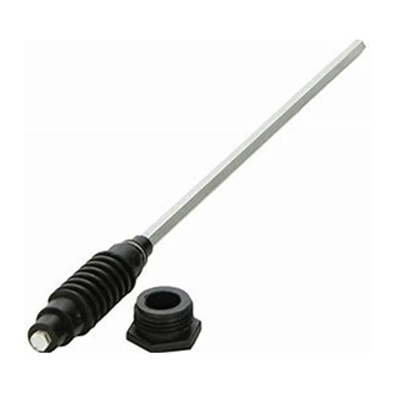
STEP 5: Temporarily mount lift/gear housing
unit on roof, Figure 2. Measure elevating shaft,
Mark length on shaft and remove lift/gear
housing from roof. Cut shaft to length marked,
Figure 3.
After cutting elevating shaft, measure length,
Figure 4, for proper cutting of directional
handle. Cut directional handle to proper length,
Figure 4.
If EK-1036 (directional handle extension) is
used, see Figure 5. DO NOT CUT EK-1036
extension. Cut excess length from directional
handle only.
IMPORTANT: The handle and extension
should be glued together after checking to be
sure you have the correct length. The handle
will not work properly if it is not glued together!
(PVC glue is recommended; for your safety,
use according to manufacturer's directions.)
®
MADE IN U.S.A.
FIGURE 2
1-1/2"
FIGURE 4
Directional Handle
NOTE: Measure from
the bottom of the
recess on top of
handle & cut to
proper length
1
®
FIGURE 1
∗ ∗ ∗ ∗ ∗
FIGURE 3
Length to cut
directional
handle
FIGURE 5
EK-1036
Extension
Measure
from bottom
of recess on
top of handle
Installation/Operation 2452035
10" Minimum
Distance
2-1/4"
DO NOT CUT
extension
Cut excess
length from
directional
hande
Advertisement
Table of Contents

Related Manuals for Winegard SENSAR RV-3090


Summary of Contents for Winegard SENSAR RV-3090
- Page 1 Distance mounting the antenna. A reinforced roof area, or a prewired coax cable, may be available. For sloped/round roofs, use Winegard Model RW-2000 exterior roof wedge, to level installation. An interior wedge, IW-5000, is also available.
-
Page 2: All Models
ALL MODELS STEP 6: Attach antenna head to lift tubes with two Leveling Bracket (2) steel pins, Figure 6. Align holes in leveling bracket on back of antenna head with holes in lift Antenna tubes, insert pins and secure in place with (2) E-clips. Head Use pliers and get a firm grip on E-clips. - Page 3 AMPLIFIED MODELS ONLY STEP 12: Select location for wall plate. Run two coax cables (RG-59 type) (three if set 2 jack is going to be used) between locations and install connectors on each end. Mark cables so "cable input", "TV output"...
-
Page 4: Operation (All Models)
OPERATION (All Models) LUBRICATION RAISING ANTENNA TO OPERATING POSITION STEP 1: To lubricate the elevating gear, apply a liberal amount of silicone spray lubricant to the elevating gear with the lift in the down position (see illustration). Run the lift up and down to distribute the lubricant over gears. -
Page 5: Test Point
INSTALLING F-CONNECTORS ON COAXIAL CABLE Step 1. Strip outer cover back 1/2"* from end of cable. Fray braid back as far as outer cover will allow. Step 2. Trim braid close to outer cover and remove 1/4"* of inner insulation being careful not to nick center conductor. -
Page 6: Ordering Repair Parts
Repair parts are available at many RV dealers and/or service centers throughout the country. If you don't have a dealer/service center near you, call Winegard Company at 1-800-288-8094. All major credit cards accepted. Parts are available only in the packages shown here. Order by the Model No. of the package needed. - Page 7 RV-3090/4090/5090 TEMPLATE 1/2" DIA. (Template) NOTE: DO NOT DRILL THOUGH CEILING IN EXPOSED AREA. 1-3/4" DIA. DRILL COMPLETELY THROUGH CEILING TOWARD FRONT OF VEHICLE 1/8" DRILL BIT 10 HOLES. DO NOT DRILL THROUGH CEILING. MINIMUM OF 5 FT. CLEAR SPACE...
- Page 8 Winegard Company warrants this Winegard product against any defects in materials or workmanship within two (2) years from date of purchase. No warranty claim will be honored unless at the time the claim is made, you present proof of purchase to an authorized Winegard dealer (if unknown, please contact Winegard Company, 3000 Kirkwood Street, Burlington, Iowa 52601-2000, telephone 319-754-0600).
Need help?
Do you have a question about the SENSAR RV-3090 and is the answer not in the manual?
Questions and answers