Table of Contents
Advertisement
Quick Links
Pro-Master
252 / 260 / 272
Owner/Operator Manual
Návod k obsluze
Instruktionsbog
Manual del propietario/operador
Betriebsanleitung
Manuel du propriétaire/utilisateur
Manuale del proprietario/operatore
Gebruikshandleiding
Brukerhåndbok
Instrukcja obslugi / operatora
Manual do Proprietário/Operador
Руководство владельца/
пользователя
Príručka majiteľa/obsluhy
Käyttöohjekirja
Instruktionsbok
Kullanım Kılavuzu
®
992316 – PM260Z
(SN 006500 +)
992317 – PM260Z
(SN 006500 +)
992321 – PM272Z
(SN 006500 +)
992322 – PM252Z
(SN 006500 +)
992324 – PM260Z RD
(SN 000101 +)
Models
US Patent 6,301,864
04329100A 3/13
Printed in USA
Advertisement
Table of Contents

Subscribe to Our Youtube Channel
Related Manuals for Ariens Gravely Pro-Master 252


Summary of Contents for Ariens Gravely Pro-Master 252
- Page 1 ® Pro-Master 252 / 260 / 272 Models Owner/Operator Manual 992316 – PM260Z Návod k obsluze (SN 006500 +) 992317 – PM260Z Instruktionsbog (SN 006500 +) Manual del propietario/operador 992321 – PM272Z Betriebsanleitung (SN 006500 +) 992322 – PM252Z Manuel du propriétaire/utilisateur (SN 006500 +) Manuale del proprietario/operatore 992324 –...
- Page 2 Nous, soussignés ARIENS COMPANY, certifions que : Der Unterzeichnete, ARIENS COMPANY, bescheinigt, dass: Wij, de ondergetekenden, ARIENS COMPANY, verklaren dat: Undertegnede, ARIENS COMPANY, attesterer, at: La sottoscritta società ARIENS COMPANY certifica che: Nosotros, los abajo firmantes, ARIENS COMPANY, certificamos que: Undertegnede, ARIENS COMPANY, bekrefter at: Undertecknad, ARIENS COMPANY, intygar att: Allekirjoittanut, ARIENS COMPANY, vakuuttaa, että: My, nijej...
- Page 3 Date Date Datum Technical File) / Directeur Conformité et Garantie des Datum Dato Data produits (Gardien du fichier technique) / Direktor Fecha Dato Ariens Company Produktkonformität und Gewährleistung Datum Päiväys (Aufbewahrungsstelle der technischen Dokumentation) / Data Data Datum Brillion, WI 54110-0157 USA...
-
Page 4: Table Of Contents
TABLE OF CONTENTS Safety ......6 Storage ......35 Assembly . - Page 5 Gravely. manual. 4. Review recommended lubrication, maintenance, and adjustments. 5. Fill out Product Registration Card and return the card to Ariens Company or go to www.gravely.eu. EN - 5...
-
Page 6: Safety
SAFETY WARNING: This cutting machine WARNING: POTENTIALLY is capable of amputating hands HAZARDOUS SITUATION! If not and feet and throwing objects. avoided, COULD RESULT in Failure to observe the safety death or serious injury. instructions in the manuals and on decals could result in serious injury or death. - Page 7 SAFETY DECALS AND LOCATIONS ALWAYS replace missing or damaged safety decals. Refer to Figure 2 for Safety Decal locations. 07700107 OD002 Figure 2 1. DANGER! TO AVOID SERIOUS NEVER CARRY CHILDREN. INJURY OR DEATH Read Operator’s Manual. OL4480 Go up and down slopes, not OL1801 across.
- Page 8 2. PINCH POINT! Look for these symbols to point out important safety Avoid pinch points. precautions. They mean: • Attention! OL3030 • Personal Safety Is OL4900 Involved! • Become Alert! 3. WARNING! • Obey The Message! Keep people away from unit Always stand clear of discharge while operating.
- Page 9 Emission controls and steep slopes or near drop components can only be adjusted by an offs Ariens Company dealer or an authorized • Avoid sharp and/or quick engine manufacturer's service center. turns Contact your Ariens Company Equipment •...
- Page 10 Data indicates that operators, age 60 and Fumes from the engine exhaust can cause above, are involved in a larger percentage of death or serious injury. DO NOT run engine in riding mower related injuries. These an enclosed area. Always provide good operators should evaluate their ability to ventilation.
- Page 11 Never direct discharge towards persons or • Do not wear a seat belt while property that may be injured or damaged by operating the unit with the center bar thrown objects. Use extreme caution on in the lowered position. gravel surfaces. •...
- Page 12 NO smoking, NO sparks, NO flames. ALWAYS block wheels and know all jack ALWAYS allow engine to cool before stands are strong and secure and will hold servicing. weight of unit during maintenance. NEVER fill fuel tank when engine is running Release pressure slowly from components or hot from operation.
-
Page 13: Assembly
ASSEMBLY Check Engine Oil WARNING: AVOID INJURY. Read Refer to Engine Manual. and understand entire Safety Check Hydraulic Oil section before proceeding. See Checking Hydraulic Oil Level on page 34. Check Coolant Level Unpack Unit Refer to Engine Manual. Remove unit and all other components from shipping container. -
Page 14: Controls And Features
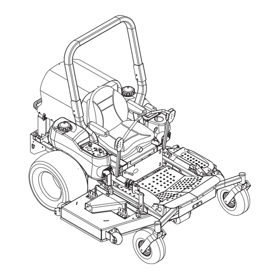
CONTROLS AND FEATURES 11, 13 OF3223 Figure 3 EN - 14... -
Page 15: Operation
1. Hood 16. Belt Cover 2. Parking Brake Lever 17. Headlights 3. Steering Levers 18. Fuel Tanks 4. Mower Lift Lever 19. PTO (Power Take-Off) Switch 5. Seat Adjustment Lever 20. Glow Plug Light 6. Seat Suspension Adjustment Knob 21. Ignition Switch 7. - Page 16 Ignition Switch Glow Plug Light Indicates when the engine glow plugs are Operate the ignition energized. Glow plugs energize for switch with the approximately 5 seconds when the key removable key. The switch is turned to the Run position. switch has three positions: Off (1), Run Fuel / Water Separator Light (2) and Start (3).
- Page 17 Parking Brake Lever Display Engages (2) and disengages (1) parking brake. Mower Lift Lever Raises and lowers mower deck. To lower (1) – Move Toggle Button mower lift lever Fuel Shut-Off Valve forward. Controls fuel flow from left fuel tank (1) or right fuel tank (2).
- Page 18 Seat Suspension Adjustment Knob IMPORTANT: Do not weld, cut, drill or modify ROPS in any manner unless instructed by the To make seat more firm turn knob clockwise. manufacturer. To make seat less firm turn knob counter Lower Center Bar clockwise.
- Page 19 8. Check Radiator Screen IMPORTANT: Refer to Engine Manual for correct type and grade of fuel. Check radiator screen for debris see Notice: If unit runs out of fuel on diesel Maintenance Schedule on page 21 and refer models , the engine must be primed prior to to Engine Manual for detailed instructions.
- Page 20 TRANSPORTING UNIT IMPORTANT: Never engage the PTO if the mower is plugged with grass or other ALWAYS shut off engine, set parking brake, material. and remove key when transporting unit on a 3. Engage PTO to engage mower blades. truck or trailer. Tie unit down securely. Do not 4.
-
Page 21: Maintenance Schedule
MAINTENANCE SCHEDULE Proper maintenance can prolong the life of unit. The following chart shows the WARNING: AVOID INJURY. Read recommended service schedule. More and understand entire Safety frequent service may be required due to section before proceeding. working conditions (heavy loads, high ambient temperatures, dusty conditions, or airborne debris). - Page 22 Interval Task Action Clean Cooling Remove dirt and debris from cooling system parts including radiator screen, oil cooler, hoses, fan, and any other parts as System detailed in the Engine Manual. IMPORTANT: More frequent cleaning may be required in dusty and dry contidions. Each IMPORTANT: To avoid damaging the radiator, DO NOT USE high-pressure water to clean the radiator.
-
Page 23: Service And Adjustments
SERVICE AND ADJUSTMENTS LUBRICATING UNIT Gravely Dealers will provide any service which may be required to keep your unit operating at peak efficiency. Should engine service be required, it can be obtained from a Gravely Dealer or the engine manufacturer’s authorized service center. - Page 24 Charging the Battery (Figure 9) WARNING: FROZEN BATTERIES CAN EXPLODE and result in death or serious injury. DO NOT charge a frozen battery. Let battery thaw before charging. Follow First Aid directions for contact with battery fluid. • External Contact: Flush with water. •...
- Page 25 MOWER BLADES Removal (Figure 11) Notice: If mower is used under sandy soil conditions, replace mower blades when air lifts become eroded through at ends CAUTION: Mower blades are (Figure 12). sharp and can cut you. Wrap All Mower Blades mower blades or wear gloves, and (992316, 317, 321, 322) use extra caution when servicing.
- Page 26 SHARPENING MOWER BLADE 3. Check mower blade balance. Slide mower blade on an unthreaded bolt. A (Figure 12) balanced blade should remain in a Notice: If mower is used under sandy soil horizontal position. If either end of conditions, replace mower blades when air mower blade moves downward, sharpen lifts become eroded through at ends.
- Page 27 Installation 5. Measure the distance between the ground and cutting edge of the blade on (Figure 14) the left blade (Left position in figure 16) 1. Slide mower deck under unit. and on the right blade (Right position in 2. Install mower mounting arms on frame. figure 16).
- Page 28 MOWER DRIVE BELT AND PTO Blade Side-to-Side Level BELT ACCESS Left Right 1. Lower the mower deck. 2. Place seat in most rearward position. 3. Place foot board in open position (Figure 18). 4. Secure raised footboard with latch. Blade Front-to-Back Pitch Front Rear Rear...
- Page 29 Notice: The PTO idler spring length range is 31,4 – 32,1 cm measured at a 7,6 cm cutting CAUTION: Use care when height. Adjust the idler spring length as releasing idler spring tension. needed (Figure 20). Keep body parts well away from 5.
- Page 30 992324 Idler Springs Length 992324 Measure idler springs length here. The idler springs length range is 35,24 – 1. PTO Belt OF3229 35,87 cm measured at a 7,6 cm cutting 2. Eye Bolt height. Adjust as necessary. 3. Springs 4. Drive Belt Idler Figure 22 5.
- Page 31 Installation TRANSMISSION BELT (Figure 19) Removal 1. Install the new mower drive belt on (Figure 23) center blade spindle pulley, right blade 1. Place unit in the service position (see spindle pulley, and drive belt idler. Service Position on page 23). 2.
- Page 32 STEERING CONTROL Eliminating Excessive Creeping of the Unit NEUTRAL ADJUSTMENT (Figure 24) If the steering levers do not line up (match) or the unit has excessive creeping when the steering levers are in neutral, adjust as WARNING: This adjustment follows. requires operating engine and Adjusting the Steering opening the hood.
- Page 33 ADJUSTING UNIT TO TRACK STEERING LEVER HANDLE STRAIGHT HEIGHT ADJUSTMENT (Figure 25) (Figure 26) The handles have three height positions. WARNING: Prior to adjusting the tracking of the unit, shut off engine, engage parking brake, and remove the ignition key. Check and adjust tire pressure.
- Page 34 Check Adjustment HYDRAULIC OIL SYSTEM (Figure 27) Notice: Be sure to check parking brake on WARNING: HYDRAULIC FLUID both sides of unit. can result in severe burns. Fluid in hydraulic system can penetrate Notice: The clearance between jam nuts skin and result in serious injury or and trunnion should be 3,2 cm.
-
Page 35: Storage
Changing Hydraulic Oil and Filter Changing Coolant Notice: Change the hydraulic oil filter and Refer to Engine Manual for the correct hydraulic oil every 400 hours. Use Mobil 1 procedure on when and how to change the Extended Performance 15W50 Synthetic Oil coolant. -
Page 36: Troubleshooting
TROUBLESHOOTING PROBLEM PROBABLE CAUSE CORRECTION Engine does not crank. 1. PTO engaged. 1. Disengage PTO. 2. Parking brake 2. Engage parking brake. disengaged. 3. Loose or corroded 3. Clean and tighten battery cables. battery cables (see Servicing The Battery on page 23). 4. - Page 37 TROUBLESHOOTING PROBLEM PROBABLE CAUSE CORRECTION PTO or mower blades 1. Operator presence 1. Depress operator switch not depressed. presence switch by do not engage or shuts sitting on seat. off. 2. Faulty PTO switch. 2. See your Gravely Dealer. Unit does not drive. 1.
-
Page 38: Accessories
SERVICE PARTS ACCESSORIES Part No. Qty Description Part No. Description 04147700 2 60" Rear Discharge Blade, 79101000 Solid Tire Kit Left and Center (992324) 79202700 Headlight Kit 04169200 1 60" Rear Discharge Blade, Right (992324) 79204200 Anti-Scalp Wheel Kit 09290500 3 72"... -
Page 39: Specifications
SPECIFICATIONS Model Number 992316 992317 Model PM260Z PM260Z Engine Daihatsu Diesel Engine Model Number 950D 950DT Governed RPM (May be different 2700 from maximum RPM) Liquid or Air Cooled Liquid Cooling System Capacity Refer to Engine Manual Speed Forward Maximum – km/h 17,7 Reverse Maximum –... - Page 40 SPECIFICATIONS Model Number 992316 992317 Model PM260Z PM260Z Maximum Towing Capacity – kg Maximum Tongue Weight – kg CE Sound and Vibration (Ref. EN836-2001) Oper. Ear Sound Pressure (Lpa) in dBA Vibration Measure (m/sec2) at Operator Hands Vibration Measure (m/sec2) at Operator Seat EN - 40...
- Page 41 SPECIFICATIONS Model Number 992321 992322 992324 Model PM272Z PM252Z PM260Z RD Engine Daihatsu Diesel Engine Model Number 950DT 950D Governed RPM (May be different 2750 2700 2850 from maximum RPM) Liquid or Air Cooled Liquid Cooling System Capacity Refer to Engine Manual Speed Forward Maximum –...
- Page 42 SPECIFICATIONS Model Number 992321 992322 992324 Model PM272Z PM252Z PM260Z RD Maximum Towing Capacity – kg Maximum Tongue Weight – kg CE Sound and Vibration (Ref. EN836-2001) Oper. Ear Sound Pressure (Lpa) in dBA Vibration Measure (m/sec2) at Operator Hands Vibration Measure (m/sec2) at Operator Seat EN - 42...
-
Page 43: Warranty
Ariens Company (Ariens) warrants to the original purchaser that Ariens, Gravely and Countax brand products purchased on or after 1/1/2012 and designated or labeled commercial products by Ariens Company will be free from defects in material and workmanship for the time period noted in the chart below. Equipment put to personal use around a single household or residence is considered "Consumer Use";... - Page 44 Exclusions – Items Not Covered by This Warranty • Parts that are not genuine Ariens, Gravely or Countax service parts are not covered by this warranty and may void the warranty. • Damages resulting from the installation or use of any part, accessory, or attachment which is not approved by the Ariens Company for use with product(s) identified herein are not covered by this warranty.
- Page 45 Disclaimer Ariens Company may from time to time change the design of its products. Nothing contained in this warranty shall be construed as obligating the Ariens Company to incorporate such design changes into previously manufactured products, nor shall such changes be construed as an admission that previous designs were defective.
- Page 46 ® Gravely 655 West Ryan Street Brillion, WI 54110 920-756-4688 Fax 920-756-2407 www.gravely.eu...
Need help?
Do you have a question about the Gravely Pro-Master 252 and is the answer not in the manual?
Questions and answers