
Subscribe to Our Youtube Channel
Related Manuals for Fagor DRO 400i


Summary of Contents for Fagor DRO 400i
- Page 1 DRO 400i Installation / Operation Manual Manual code: 14460377 Manual version: 2405 Software version: v1.00...
-
Page 3: Table Of Contents
INDEX DRO description ......................5 Front plate........................5 Turning the unit on and off..................... 5 Main screen description ....................6 Function bar........................6 1.4.1 Accessing functions in MILL mode ......................6 1.4.2 Accessing the functions in LATHE mode ....................6 DRO operation in MILL mode .................. - Page 4 5.2.4 Returning conditions ..........................39 Maintenance........................39 IMPORTANT NOTE Some of the features described in this manual may not be available in this version. Consult with the Fagor Automation branch office nearest you. (4/40) - Installation / Operation - 400i...
-
Page 5: Dro Description
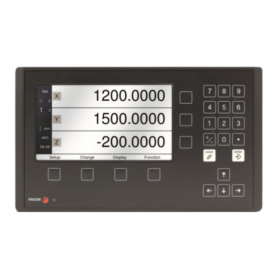
1 DRO description 1.1 Front plate * Select axes Keys for entering numeric values * Delete axis * Preset 7" color screen Switch between Z, Z1 and Z2 in 3-axis lathe mode. Validate the access to SET * Abort an operation already initiated * Delete axis. -
Page 6: Main Screen Description
1.3 Main screen description STATUS BAR DISPLAY AREA Set/Clear Active reference Nr Active tool Nr Display units mm/inch Display mode: INC/ABS Chronometer FUNCTION BAR Setup Change Display Function 1.4 Function bar The function bar gives access to the various functions offered by the DRO. 1.4.1 Accessing functions in MILL mode Setup... -
Page 7: Dro Operation In Mill Mode
2 DRO operation in MILL mode 2.1 Display modes Display 2.1.1 mm / inch Display mm / inch Toggle units between mm and inches. This toggle is possible if the installer parameters have been set as toggle. 2.1.2 inc / abs Display inc / abs Toggle between incremental and absolute feedback reading (counting). -
Page 8: Degrees / Degrees-Minutes-Seconds
2.1.2.3 Degrees / Degrees-Minutes-Seconds Display Deg / DMS Toggles the axis display units between degrees and degrees, minutes, seconds. 2.1.3 Rad / Diam Display Rad / Diam Toggles the X axis display between radius and diameter. 2.2 Set/Clear Display Set/Clear There are two ways (modes) to set a value (Set) on the display or zero it (Clear). -
Page 9: Machine Reference (Home) Search
2.3 Machine reference (home) search Setup Home search Select axis. A red bar appears on that axis display indicating that it is waiting for a reference pulse. Move the selected axis until the DRO detects the reference mark. A green checkmark appears next to the axis display when the reference mark is properly detected (homed) and the axis display will show the position value preset in parameter "user... -
Page 10: Tool Compensation
2.4.1.3 Tool compensation This DRO offers a function for compensating tool radius depending on the machining direction. Tool compensation on /off in this direction: Tool compensation on /off in this direction: Tool compensation on /off in this direction: Tool compensation on /off in this direction: When machining pockets, tool radius compensation is activated in two axes at the same time. -
Page 11: Changing The Reference
2.4.2.1 Changing the reference Change Reference Changing from one reference to another. Ref. no. It changes to the selected reference. 2.4.2.2 Setting part zero (datum) as instructed by the assistant: Change Reference Origin Setting part zero requires measuring at least 2 Reference points. -
Page 12: Setting Part Zero (Datum) Without Using The Assistant
2.4.2.3 Setting part zero (datum) without using the assistant Change Reference Set a datum point at a corner other than the 3rd quadrant. Compensate for tool radius on the X axis. Touch with the tool on the side indicated in the figure. Set the X axis to zero. -
Page 13: Special Functions
2.5 Special functions Function It gives access to the specific milling functions. 2.5.1 Bolt-hole drilling Function Bolt-hole drilling It allows up to 99 holes to be drilled in a bolt-hole Bolt-hole drilling pattern in different planes (XY, XZ, YZ) without Plane having to calculate the coordinates (X Y) of each hole, by simply keying in some basic data. -
Page 14: Grid Pattern Drilling
2.5.3 Grid pattern drilling Function Grid pattern drilling It allows up to 99 holes to be drilled in grid or Grid pattern drilling frame pattern in different planes (XY, XZ, YZ) Plane without having to calculate the coordinates (X Y) of each hole, by simply keying in some basic Type data. -
Page 15: Calculator Function
2.5.5 Calculator function Function Calculator It may be used to carry out mathematical and Calculator Calculator trigonometric operations as well as preset the desired axis with the result of the calculation or import the displayed coordinate values into the calculator to carry out math operations. Different types of calculators may be selected at the function bar: Arithmetic, trigonometric and for square functions. -
Page 16: Cycle Execution
2.5.6.2 Cycle execution Pressing the Run key, the DRO shows the distance the axes must move to position at the first hole. Move the axes to zero. The status bar indicates the number of the current hole and the total number of holes programmed in the cycle. -
Page 17: Probe
The probe stores the data about the probed points in a USB memory. The probing data may be read and processed at a PC. The file containing the probed points is: FAGOR/DRO/PROBE/probe.csv The format of the generated file is “csv” (comma separated values) and may be easily imported into a spreadsheet. - Page 18 (18/40) - Installation / Operation - 400i...
-
Page 19: Dro Operation In Lathe Mode
3 DRO operation in LATHE mode 3.1 Display modes 3.1.1 2/3 axes Display 2/3 axes Toggle the reading of the second axis between Z (Z1 + Z2), Z1 or Z2, when the DRO has been set for 3-axis lathe. When it has been set by parameter to only display the Z axis, this key toggles between displaying 2 axes (X, Z) and displaying 3 axes (X, Z1, Z2). -
Page 20: Incremental Mode
3.1.4.2 Incremental mode The coordinate is referred to the previous point where the axis display has been set to zero. Set the dro in incremental mode. Set a floating zero (Z=0) at point A. Preset the value “22.6” for the Z axis. Run several passes moving the Z axis to zero until reducing it to the desired diameter. -
Page 21: Setting The Tool By Touching A Part Of Known Diameter
3.2.1.1 Setting the tool by touching a part of known diameter Enter tool number. Press Enter. Move the X axis until the tool touches the part. Preset the part diameter. Move the Z axis until the tool touches the part. Preset the value for the Z axis. -
Page 22: Angle Calculation
3.3.2 Angle calculation Function Angle calculation Calculate the angle, knowing the diameters and Angle calculation the length between them. Diameter 1 Diameter 2 Length Help 3.3.3 Turning function Function Turning Assistant for defining a turning cycle after having Turning entered the following data: Axes X: Starting diameter. -
Page 23: Dro Installation
4 DRO installation There are two ways to mount the DRO 400i: 1- Mounted on the support arm. 2- Built-in model. 4.1 Mounting on the support arm The DRO may be mounted at the desired height and may be oriented at will. -
Page 24: Dimensions Of The Display, The Bracket And Of The Window To Insert It Into
4.3 Dimensions of the display, the bracket and of the window to insert it into The first figure shows the DRO dimensions. The second figure shows the dimensions of the hole needed in the enclosure of the machine to built this model into. The dimensions of the bracket where the arm is mounted are shown in the third figure. -
Page 25: Rear Panel
4.4 Rear panel X1-X3 On the back of the unit the following items may be found: • Three-prong power connector for AC and ground connection. • On/off switch. • M6 mm terminal, for general machine ground connection. • Mounting bracket •... -
Page 26: General Technical Characteristics
4.5 General technical characteristics - Universal Power Supply between 100V AC and 240V AC ±10% at a mains frequency between 50 Hz and 60 Hz, between 140 V DC and 340 V DC. Maximum power consumed 25 VA. It withstands power outages of up to 10 milliseconds. -
Page 27: Connections
4.6 Connections 4.6.1 Connection of the feedback systems The feedback systems (linear or rotary encoders) are connected via SUB-D HD type 15-pin female connectors: X1 through X3. Characteristics of feedback inputs: X1, X2 and X3: -Maximum feedback consumption: 250 mA at the +5V input. -Admits square-wave signal (TTL). -
Page 28: Probe Connection (Connector X6)
4.6.2 Probe connection (connector X6) Either a 5 V or a 24 V probe may be connected. Characteristics of probe inputs X6: 5V probe input Typical value 0,25 mA. Vin = 5 V. High threshold (logic level "1") VIH: From +2.4 V DC on. Low threshold (logic level "0") VIL: Below +0.9 V DC. -
Page 29: Power And Machine Connection
Interface with an open-collector output. Connection to +5 V. Acts with a down flank. Interface with an open-collector output. Connection to +24 V. Acts with a down flank. Interface with a PUSH-PULL output The active flank depends on the interface used 4.6.3 Power and machine connection Always mount it vertically so its keyboard is within operator's reach and its digits are easily visible (at... -
Page 30: Installation Parameters
4.7 Installation parameters 4.7.1 Accessing installation parameters Setup Home search Configuration User Test Installer Password 231202 Language Color Feedback Compensation (type, axes, (linear, alarms) (encoders) multi-point) Setup Configuration Gives access to setting installation and user parameters and to the test mode. The parameter setup is divided into three parts: Configuration 1- USER PARAMETERS: Parameters that may... -
Page 31: Screen Color
4.7.2.2 Screen color The colors of the background and numbers on the main screen can be changed. There is also the ColorSet option to restore the original colors. 4.7.2.3 Chronometer Chronometer It is possible to turn the stopwatch on or off. As well as to restart your account or set a number. 4.7.2.4 Sound Sound It is possible to turn the keystroke sound on or off. -
Page 32: Dro
4.7.3.2 DRO Setup Configuration Install It configures the DRO for each type of machine: Number of axes, type of machine (mill, lathe, etc.). Pressing this button opens the window shown on DRO Parameters the right. The following items are set in it: Type of Machine Lathe 1- Type of Machine: Mill or lathe. -
Page 33: Feedback
4.7.3.3 Feedback Setup Configuration Install Feedback FAGOR Selecting Fagor feedback knowing the name or model of the linear encoder. Select axis. Fagor Feedback Parameters Select type of linear encoder, type of signal and type of reference pulse. Series To validate the data for that axis. - Page 34 1Vpp or TTL with distance-coded reference marks. Example: We wish to install a FAGOR GP linear encoder (1 Vpp and 20-micron-pitch graduated glass) with 1 micron resolution: Graduation pitch (20, 40 or 100 µm)
-
Page 35: Compensation
Reference Setup Configuration Install Feedback Reference This window sets the parameters related to home search and the type of reference mark of the encoder. This configuration must be set for each axis. * User offset: Offset of the reference point with Reference Marks respect to the reference zero of the feedback device, independent for each axis. -
Page 36: Test Mode
Important: Before capturing data for an accuracy graph, Error compensation a home search must be carried out because Select compensation type Multipoint the compensation will not be applied until the Multipoint Compensation home search is done. To use this compensation, Point Position Error... -
Page 37: Appendix
The DRO must not be powered-on until verifying that the machine complies with the "2006/42/EC" Directive. 5.2.1 Declaration of conformity The declaration of conformity for the DRO is available in the downloads section of FAGOR’S corporate website at http://www.fagorautomation.com. (Type of file: Declaration of conformity). 5.2.2 Safety conditions Read the following safety measures in order to prevent harming people or damage to this product and those products connected to it. - Page 38 Do not work in explosive environments. In order to avoid risks, harm or damages, do not work in explosive environments. Working environment. This unit is ready to be used in Industrial Environments complying with the directives and regulations effective in the European Community. It is recommended to mount the DRO vertically, so its power switch of the back panel is at a distance between 0.7m (27.5 inches) and 1.7m (5.6 ft) off the floor and away from coolants, chemical products, blows etc that could damage it.
-
Page 39: Warranty Terms
The cardboard being used to make the box must have a resistance of 170 Kg (375 lb.). When sending it to a Fagor Automation office for repair, attach a label indicating the owner of the unit, person to contact, type of unit, serial number, symptom and a brief description of the problem. - Page 40 FAGOR AUTOMATION S. COOP. Bª San Andrés Nº 19 Apdo de correos 144 20500 Arrasate/Mondragón - Spain - Web: www.fagorautomation.com Email: contact@fagorautomation.es Tel.: (34) 943 039800 Fax: (34) 943 791712 (40/40) - Installation / Operation - 400i...
Need help?
Do you have a question about the DRO 400i and is the answer not in the manual?
Questions and answers