Advertisement
Quick Links
Advertisement

Related Manuals for Verkada Command Connector


Summary of Contents for Verkada Command Connector
- Page 1 Install Guide CC300 CC500 CC700 Command Connector...
-
Page 2: Product Models
Verkada product is granted under this document. This document may not be sold, resold, licensed or sublicensed and may not be transferred without Verkada’s prior written consent. No part of this document may be reproduced in whole or in part without the express written consent of Verkada. -
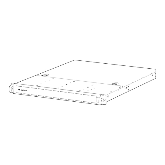
Page 3: Introduction What's In The Box
What’s in the box Terminal Block M5x6mm Rack Mount Screws (8 pcs - attached to Mount Rails) M4x6mm Flat Head Screws (4 pcs) Command Connector M5x15mm Truss Head Screws 60cm Mount Rails (2 pcs) (2 pcs) (80cm ordered separately) Front Cover Power Cord... - Page 4 Introduction Overview Rack Ear Front Cover Release Switch Connector 2x USB Power HDD 1 HDD 2 HDD 3 HDD 4 Display Port 1.4 2x LAN Terminal Block Audio In/Out AC Power HDMI 1.4 HDMI 2.0 4x USB Mic In...
- Page 5 M5x10mm Truss Head Screws (6 pcs) Note: Two Post Server Rack If installing on a 2 post server rack, Verkada recommends using a 2 post rack rail kit or a server rack shelf to support the Command Connector unit. Please contact Verkada.com/support...
- Page 6 Installation Outer Mount Rail (1/2) Remove the inner mount rail from the outer mount rail. Loosen screws highlighted in the image. Do not remove them completely. Remove the front and rear screws.
- Page 7 Installation Outer Mount Rail (2/2) Extend the outer outer mount rail to match the depth between the server rack posts. Insert and tighten the front and rear screws. See the Server Rack Post Mounting Guidance section for mounting screw guidance. Tighten the screws highlighted in the image.
- Page 8 Installation Front Cover Removal Slide the release switch to the left to disengage the front cover mount pins from the right rack ear. Swing the right side of the front cover away from the Connector to disengage the front cover mount pins from the left rack ear and set aside.
- Page 9 Installation Inner Mount Rail To install the inner mount rail to the Connector, align the holes on the inner rail with the posts on the side of the Connector. Slide the inner mount rail away from the front of the device to engage the posts.
- Page 10 Installation Connector Mounting Align the inner mount rails on both sides of the Connector with the outer mount rails installed on the server rack and insert the Connector by sliding inward. The Connector installation on the server rack is complete.
- Page 11 Installation Front Cover Install Align pins on the left side of the front cover with the holes on the left rack ear and insert. Slide the release switch to the left to depress the mount pins on the right side of the front cover. Swing the right side of the front cover so the mount pins on the right side align with the holes on the right rack...
-
Page 12: Hdd Replacement
Installation HDD Replacement (1/4) Push the button to the right of the blue stripe to release the HDD caddy door. Gently remove the HDD caddy from the central unit. Flip over the HDD caddy. - Page 13 Installation HDD Replacement (2/4) Locate the green release lever and push down, rotating 90 degrees counterclockwise, to disengage the lock mechanism. Then, flip the caddy back over. Slide the HDD towards the front of the caddy by gently pushing on the back side of the HDD.
- Page 14 Installation HDD Replacement (3/4) Insert replacement HDD by aligning HDD with the caddy rails. Gently slide in from the back side until it clicks into place. Rotate the green lever down until it clicks into place to secure the HDD in the caddy.
- Page 15 Installation HDD Replacement (4/4) Gently push the caddy into the main device until it is secure. Rotate the front door back into its original position until it clicks into place.
- Page 16 Appendix Compliance This equipment has been tested and found to comply with the limits for a Class A digital device, pursuant to part 15 of the FCC Rules. These limits are designed to provide reasonable protection Compliance against harmful interference when the equipment is operated in a commercial environment. This equipment generates, uses, and can radiate radio frequency energy and, if not installed and used in accordance with the instruction manual, may cause harmful interference to radio communications.
- Page 17 Appendix Support Thank you for purchasing this Verkada product. If for any reason you're experiencing issues or need assistance, please contact our 24/7 Technical Support Team immediately. Sincerely, The Verkada Team verkada.com/support...
Need help?
Do you have a question about the Command Connector and is the answer not in the manual?
Questions and answers