Table of Contents
Advertisement
M3 Starter Kit
H3 Starter Kit
All information contained in these materials, including products and product specifications,
represents information on the product at the time of publication and is subject to change by
Renesas Electronics Corp. without notice. Please review the latest information published by
Renesas Electronics Corp. through various means, including the Renesas Electronics Corp.
website (http://www.renesas.com).
www.renesas.com
Rev.1.1 Apr 2020
Advertisement
Table of Contents

Related Manuals for Renesas R-Car M3 Starter Kit


Summary of Contents for Renesas R-Car M3 Starter Kit
- Page 1 All information contained in these materials, including products and product specifications, represents information on the product at the time of publication and is subject to change by Renesas Electronics Corp. without notice. Please review the latest information published by Renesas Electronics Corp. through various means, including the Renesas Electronics Corp.
- Page 2 You may not use any Renesas Electronics product for any application for which it is not intended. Renesas Electronics shall not be in any way liable for any damages or losses incurred by you or third parties arising from the use of any Renesas Electronics product for which the product is not intended by Renesas Electronics.
- Page 3 The following usage notes are applicable to all Microprocessing unit and Microcontroller unit products from Renesas. For detailed usage notes on the products covered by this document, refer to the relevant sections of the document as well as any technical updates that have been issued for the products.
- Page 4 H3 Starter Kit / M3 Starter Kit Hardware Manual AIBD1-16-0146 Page 1 of 37 Nov 8,2016...
-
Page 5: Table Of Contents
H3 Starter Kit / M3 Starter Kit Hardware Manual Contents About this manual ........................ 3 Overview ........................4 1.1 Introduction ..............................4 1.2 H3 & M3 Starter Kit Board Major Configuration ..................5 1.3 H3 & M3 Starter Kit Board Major Specification ..................6 1.4 H3 &... -
Page 6: About This Manual
H3 Starter Kit / M3 Starter Kit Hardware Manual About this manual Purpose and Target Readers This manual is designed to provide the user with an understanding of the functions and operating specifications of the H3 & M3 Starter Kit board. A basic knowledge of electrical circuits, logical circuits, and microcomputers (SOC) is necessary in order to use this manual. -
Page 7: Overview
The H3 & M3 Starter Kit boards are designed for evaluating the features and performance of the R-CAR H3 & R-CAR M3 device from Renesas Electronics and it is also used for developing and evaluating application software for these R-CAR H3 & R-CAR The H3 Starter Kit, based on the R-CAR H3 SIP, comes with LPDDR4@4GB in 2-channel, each 64-bit wide+Hyperflash @64MB, CSI2 interfaces and several communication interfaces like USB, Ethernet, HDMI and can work standalone or can... -
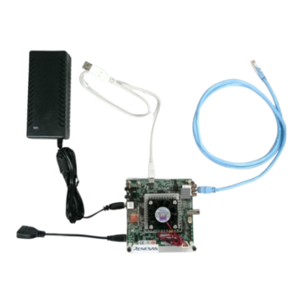
Page 8: H3 & M3 Starter Kit Board Major Configuration
H3 Starter Kit / M3 Starter Kit Hardware Manual 1.2 H3 & M3 Starter Kit Board Major Configuration The figure shows an example of a system configuration using the H3 Starter Kit Board. IGURE TANDART ONFIGURATION AIBD1-16-0146 Page 5 of 37 Nov 8,2016... -
Page 9: H3 & M3 Starter Kit Board Major Specification
H3 Starter Kit / M3 Starter Kit Hardware Manual 1.3 H3 & M3 Starter Kit Board Major Specification H3 Starter Kit M3 Starter Kit R-CAR H3 R-CAR M3 ARM CA57 (ARMv8) ARM CA57 (ARMv8) • • 1.5 GHz quad core, with NEON/VFPv4, L1$ I/D 48K/32K, L2$ 2MB 1.5 GHz dual core, with NEON/VFPv4, L1$ I/D 48K/32K, L2$ 2MB ARM CA53 (ARMv8) ARM CA53 (ARMv8) -
Page 10: H3 & M3 Starter Kit Board Block Diagram
H3 Starter Kit / M3 Starter Kit Hardware Manual 1.4 H3 & M3 Starter Kit Board Block Diagram Power eMMC DDR4 Hyper Supply FLASH DDR4 FLASH R-Car H3 DDR4 Ethernet DDR4 HDMI AUDIO ComExpress Connector 2 H3 S IGURE TARTER IT BOARD BLOCK DIAGRAM Power eMMC... -
Page 11: H3 & M3 Starter Kit Board Functions Supported
H3 Starter Kit / M3 Starter Kit Hardware Manual 1.5 H3 & M3 Starter Kit Board Functions Supported This table describes the functions available on the H3 & M3 Starter Kit board. Observe due to the pin-sharing some functions are shared and can’t be used in parallel. It’s important to check this carefully. Function Description DEBUG Serial... -
Page 12: Major Components
H3 Starter Kit / M3 Starter Kit Hardware Manual 1.6 Major Components CLPD JTAG DEBUG SERIAL Not used Ethernet MIC INPUT LINE OUT Power In USB 2.0 DDR4 JTAG DEBUG Hyperflash QSPI FLASH IF PMIC FAN CONN SOC H3 4 H3 STARTER KIT BOARD LAYOUT (TOP VIEW /COMPONENT SIDE) IGURE MICRO SD MICRO HDMI... -
Page 13: Switches Locations
H3 Starter Kit / M3 Starter Kit Hardware Manual 1.7 Switches locations SW3,4,5 6 H3 STARTER KIT BOARD LAYOUT (TOP VIEW /COMPONENT SIDE) IGURE Switches and LED’s description are on chapter 3.13-3.14 1.8 Electrical characteristic Recommended Operating Conditions Over free-air temperature range Unit DC5.0V Supply Voltage... -
Page 14: Quick Start Up Guide
H3 Starter Kit / M3 Starter Kit Hardware Manual Quick Start up Guide 2.1 Default Switch setting This table describes the Default switch setting to boot from Minimonitor program stored in on board QSPI device. Switch Switch Switch Pin1 Pin2 Pin3 Pin4 Number... -
Page 15: Procedure
H3 Starter Kit / M3 Starter Kit Hardware Manual 2.2 Procedure Connect the DC 5V and CN12 Micro USB to PC. Power ON the board by Press SW8. Then on PC, FT232 Driver is download automatically. Launch the Console(Teraterm), and set up the serial port setting [Serial port set up] Port - choose which assigned to board connection Baud rate - 115200... -
Page 16: Functions & Interfaces
H3 Starter Kit / M3 Starter Kit Hardware Manual Functions & Interfaces 3.1 Power In -------------------------------------------------------------------------------------------------------------------------------------------------- On Board: 5V/8A input PMIC for all required voltages; SEEPROM-configured Power button On ComExpress: Power-up/down by edge or level Power-good status CN13 IGURE OWER Matching Plug: Ø5.5 mm, Center pin Ø2.0 mm, Jack Insertion Depth: 8.85 mm CN13... -
Page 17: Debug Serial (Via Usb)
H3 Starter Kit / M3 Starter Kit Hardware Manual 3.3 Debug Serial (via USB) -------------------------------------------------------------------------------------------------------------------------------------------------- On Board: Standard micro USB connector The SCIF2 interface of the R-Card Device is provided over the Converter FT232RQ By default available on-board On ComExpress: Available after reassembling Note: This is not a USB Port of the SOC 9 DEBUG SERIAL... -
Page 18: Qspi Flash
H3 Starter Kit / M3 Starter Kit Hardware Manual 3.5 QSPI Flash -------------------------------------------------------------------------------------------------------------------------------------------------- On Board: 16MBytes QSPI (128 Mbits, 80 MHz, 80 MBytes/s) 1 header for QSPI module VIO=1.8V,VCC=3.3V SW1 to Switch between the Modes Hyper Flash | On: Hyperflash / Off: QSPI On ComExpress: QSPI flash memory: 1ch QSPI (Max. -
Page 19: Micro Sd-Card
H3 Starter Kit / M3 Starter Kit Hardware Manual 3.7 Micro SD-Card -------------------------------------------------------------------------------------------------------------------------------------------------- On Board: SDHI0 / MicroSD-Card slot (SDR104 100 MBytes/s) On ComExpress: SDHI3 / 1 additional SD host interface available (SDR104 104 MBytes/s) 13 M SD-C IGURE ICRO 3.8 JTAG Coresight Debug -------------------------------------------------------------------------------------------------------------------------------------------------- On Board:... -
Page 20: Ethernet
H3 Starter Kit / M3 Starter Kit Hardware Manual 3.9 Ethernet -------------------------------------------------------------------------------------------------------------------------------------------------- On Board: PHY + RJ45 connector (100/1000) On ComExpress: Alternatively to on-board PHY: RGMII V1.3 interface (2.5V) Note: For this Interface are 2 different Order codes available. 15 E IGURE THERNET 3.10 USB 2.0 host... -
Page 21: Line Out / Mic Input
H3 Starter Kit / M3 Starter Kit Hardware Manual 3.11 Line Out / MIC Input -------------------------------------------------------------------------------------------------------------------------------------------------- On Board: Stereo microphone input (AK4613 codec) Stereo line out (AK4613 codec) 17 L / MIC I IGURE NPUT 3.12 CPLD JTAG -------------------------------------------------------------------------------------------------------------------------------------------------- On Board: Interface for programming the CPLD 6-Pin 1.27 Pin Header 18 CPLD JTAG... -
Page 22: Buttons And Switches
H3 Starter Kit / M3 Starter Kit Hardware Manual 3.13 Buttons and Switches -------------------------------------------------------------------------------------------------------------------------------------------------- -------------------------------------------------------------------------------------------------------------------------------------------------- SW 1 Hyper Flash | On: Hyperflash / Off: QSPI -------------------------------------------------------------------------------------------------------------------------------------------------- SW 2 4x DIPSW Software Readable SW2.1 at GP5_17 SW2.2 at GP5_20 SW2.3 at GP5_22 SW2.4 at GP5_23 -------------------------------------------------------------------------------------------------------------------------------------------------- SW 3... - Page 23 H3 Starter Kit / M3 Starter Kit Hardware Manual -------------------------------------------------------------------------------------------------------------------------------------------------- SW 7 Reset (same as SW 9) -------------------------------------------------------------------------------------------------------------------------------------------------- SW 8 Power -------------------------------------------------------------------------------------------------------------------------------------------------- SW 9 Reset (same as SW 7) -------------------------------------------------------------------------------------------------------------------------------------------------- QSPI Selector -------------------------------------------------------------------------------------------------------------------------------------------------- AIBD1-16-0146 Page 20 of 37 Nov 8,2016...
-
Page 24: On Board Led's
H3 Starter Kit / M3 Starter Kit Hardware Manual 3.14 On Board LED’s -------------------------------------------------------------------------------------------------------------------------------------------------- -------------------------------------------------------------------------------------------------------------------------------------------------- LED1 HDMI / Hot Plug Sync Detect -------------------------------------------------------------------------------------------------------------------------------------------------- LED4 Software Controllable LED -------------------------------------------------------------------------------------------------------------------------------------------------- LED5 Software Controllable LED -------------------------------------------------------------------------------------------------------------------------------------------------- LED6 Software Controllable LED -------------------------------------------------------------------------------------------------------------------------------------------------- LED 9 5V Main Supply -------------------------------------------------------------------------------------------------------------------------------------------------- LED14... -
Page 25: Booting
H3 Starter Kit / M3 Starter Kit Hardware Manual 3.15 Booting -------------------------------------------------------------------------------------------------------------------------------------------------- The on-board QSPI flash and Hyperflash are pre-loaded with a bootloader and U-boot. It is possible to boot a Linux from Ethernet (TFTP), from a microSD card or from a USB stick. A console is available at the USB/UART CN12. -
Page 26: Jtag Sica Debug Interface
H3 Starter Kit / M3 Starter Kit Hardware Manual 3.16 JTAG SICA Debug Interface -------------------------------------------------------------------------------------------------------------------------------------------------- The JTAG debug connector for R-CAR H3 is a SICA2P0S05 20pin Port, which is to use with a SICA-Small Interface Cable Adapter. Debug interface can be directly connected to a debugger. D1.8V D1.8V TRST... -
Page 27: Board To Board Connector (Com Express 440Pin)
H3 Starter Kit / M3 Starter Kit Hardware Manual 3.17 Board to Board Connector (COM Express 440pin) -------------------------------------------------------------------------------------------------------------------------------------------------- The board to board connector on the bottom side is according the COM Express definition. The pin mapping is not identical to this standard, it’s only similar. Refer to the attached table for the H3 Starter Kit pin mapping. For the mechanical dimension please refer to the attached drawing. - Page 28 H3 Starter Kit / M3 Starter Kit Hardware Manual CSI2 length matching for custom designed add-on boards According to the MIPI Standard, the CSI2 data and clock lanes need to be length-matched, inter-lane and also inter-lane. The complete lane length from transmitter (here: add-on board) to receiver (here: H3 SoC) must be considered. This table shows the length of the signals on the H3 Starter Kit.
-
Page 29: Power Supply And Control From Add-On Boards
H3 Starter Kit / M3 Starter Kit Hardware Manual 3.18 Power supply and control from add-on boards -------------------------------------------------------------------------------------------------------------------------------------------------- By default, the board is supplied with 5V by the on-board connector (CN13). By default, the board can be turned on and off by pressing the power button (SW8). When designing a custom add-on board, it is possible to supply the board through the CoM Express connector. -
Page 30: Cpld Contents
H3 Starter Kit / M3 Starter Kit Hardware Manual 3.19 CPLD contents -------------------------------------------------------------------------------------------------------------------------------------------------- MODE pins / ExA[0 : 19], ExD[0 : 15] Mode signals MD0 to MD28 and MDT0, MDT1 multiplexed on ExA/ExD lines be latched during reset; release after reset phase (t_hold min 3ns), each mode signal is set according to Mode Pin settings. - Page 31 H3 Starter Kit / M3 Starter Kit Hardware Manual Dynamic, volatile reconfiguration via SoC, GPIOs MSIOF / MSIOF1_SCK[K6], MSIOF1_TXD[G10], MSIOF1_RXD[C10], ExA25/PWM4 Interface to SiP - MSIOF1. This figure explains serial I/F Frame format implemented in CPLD. SCLK / \__/ \__/ \__/ \__/ \__/ \__/ \__/ \__/ \__/ \__/ \__/ \__/ \__/ ___._____._____._____._____._____.__ __._____._____._____._____._____.___ SSTBZ...
- Page 32 H3 Starter Kit / M3 Starter Kit Hardware Manual REGISTER Map Register Reg. Default Default address value function Function description 0x00 free running mode pin MD00 0x00 Serial flash (QSPI U5 or external) mode pin MD01 0x00 Serial flash (QSPI U5 or external) mode pin MD02 0x00 Serial flash (QSPI U5 or external)
- Page 33 H3 Starter Kit / M3 Starter Kit Hardware Manual class A EN 55022:2010. This equipment complies with the EMC protection requirements The board code on test. Y-ASK-RCAR-M3-ETH-WS1 (M3) Y-ASK-RCAR-H3-ETH-WS1 (H3) AIBD1-16-0146 Page 30 of 37 Nov 8,2016...
-
Page 34: Appendix
H3 Starter Kit / M3 Starter Kit Hardware Manual Appendix R-Car_Gen3_StarterKit_schematic_Revxxx R-Car_Gen3_StarterKit_BOM_revxxx_(M3) R-Car_Gen3_StarterKit_BOM_revxxx_(H3) R-Car_Gen3_StarterKit_board_dimensions_drawing_xxx_revxxx_(M3&H3) R-Car_Gen3_StarterKit_board_assembly_drawing_046B_revxxx_(M3&H3) R-Car_Gen3_StarterKit_CoM_Express_Interfaces_revxxx_(M3&H3) Refer to the attachments of this Hardware Manual file. AIBD1-16-0146 Page 31 of 37 Nov 8,2016... - Page 35 May 30, 2016 First Edition issued Nov 08, 2016 Initialized for Starterkit. Draft version. Dec 21, 2016 Title name changed and updated to rev1. Apr.6, 2020 Delete “4k” and update the Renesas logo AIBD1-16-0146 Page 32 of 37 Nov 8,2016...
- Page 36 Renesas Electronics Hong Kong Limited Unit 1601-1611, 16/F., Tower 2, Grand Century Place, 193 Prince Edward Road West, Mongkok, Kowloon, Hong Kong Tel: +852-2265-6688, Fax: +852 2886-9022 Renesas Electronics Taiwan Co., Ltd. 13F, No. 363, Fu Shing North Road, Taipei 10543, Taiwan Tel: +886-2-8175-9600, Fax: +886 2-8175-9670 Renesas Electronics Singapore Pte.
- Page 37 H3 Starter Kit M3 Starter Kit R01UH0001XJ090-RCSKB...
Need help?
Do you have a question about the R-Car M3 Starter Kit and is the answer not in the manual?
Questions and answers