Vertiv XDU1350 Installation And Commissioning Manual
Coolant distribution unit
Hide thumbs
Also See for XDU1350:
- Operation and maintenance manual (96 pages) ,
- Planning manual (52 pages)
Table of Contents
Advertisement
Advertisement
Table of Contents

Subscribe to Our Youtube Channel
Related Manuals for Vertiv XDU1350


Summary of Contents for Vertiv XDU1350
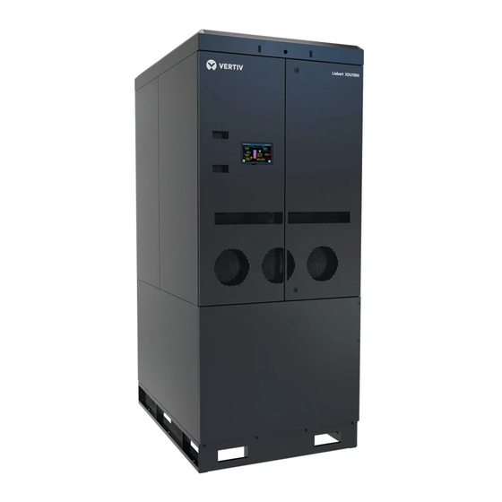
- Page 1 XDU1350 Coolant Distribution Unit Installation and Commissioning Guide XDU1350B...
- Page 2 The products covered by this instruction manual are manufactured and/or sold by Vertiv. This document is the property of Vertiv and contains confidential and proprietary information owned by Vertiv. Any copying, use, or disclosure of it without the written permission of Vertiv is strictly prohibited.
-
Page 3: Table Of Contents
Vertiv™ XDU1350 Coolant Distribution Unit Installation and Commissioning Guide TABLE OF CONTENTS 1 Important Safety Instructions 1.1 General 1.2 Installation and Handling 1.3 Application 1.4 Warranty 1.5 Electrical Connection 1.6 Replacement Parts 1.7 Waste Disposal 1.8 Documentation 2 Agency 2.1 Product Standards and Approvals 2.2 ROHS 3 Compliance... - Page 4 Vertiv™ XDU1350 Coolant Distribution Unit Installation and Commissioning Guide 6 Commissioning 6.1 Unit Configuration 6.2 Primary Circuit 6.2.1 Primary Pipework Installation 6.2.2 Facility Water Supply 6.2.3 Primary Control Valves 6.2.4 Primary Circuit Filling 6.2.5 Primary Flow Setup 6.3 Secondary Circuit 6.3.1 Secondary Pipework Connections...
-
Page 5: Important Safety Instructions
1 Important Safety Instructions Save These Instructions This manual contains important instructions that should be followed during operation and maintenance of the Vertiv™ XDU1350. WARNING! Arc flash and electric shock hazard. Can cause serious injury or death. Building and equipment damage may also result. - Page 6 Vertiv™ XDU1350 Coolant Distribution Unit Installation and Commissioning Guide WARNING! Risk of improper wire sizing/rating and loose electrical connections causing overheated wire and electrical connection terminals resulting in smoke or fire. Can cause serious injury or death. Building and equipment damage may also result. Use correctly sized copper wire only and verify that all electrical connections are tight before turning power On.
- Page 7 Vertiv™ XDU1350 Coolant Distribution Unit Installation and Commissioning Guide CAUTION: Risk of improper handling heavy and lengthy parts. Can cause injury. Building and equipment damage may also result. Cabinet panels can exceed 5 ft. (1.5 m) in length and weigh more than 35 lb. (15.9 kg).
- Page 8 Vertiv recommends installing a monitored fluid detection system that is wired to activate the automatic closure of field installed coolant fluid supply and return shut off valves to reduce the amount of coolant fluid leakage and consequential equipment and building damage.
-
Page 9: General
Vertiv™ XDU1350 Coolant Distribution Unit Installation and Commissioning Guide NOTICE Risk of a catastrophic water circuit rupture. Can cause expensive building and equipment damage. Install an overflow drain pan under the unit with a monitored leak detection system in the pan and shutoff valves in the supply and return water lines that automatically close if water is detected by the leak detection system. -
Page 10: Installation And Handling
This product is to be used indoors only and must be only used for the application it was designed for. This product must not be used in a hazardous environment. 1.4 Warranty Failure to comply with the Vertiv installation, maintenance, and operation instructions may affect the reliability and performance of the unit and invalidate any warranty. 1.5 Electrical Connection WARNING! Arc flash and electric shock hazard. -
Page 11: Replacement Parts
Vertiv™ XDU1350 Coolant Distribution Unit Installation and Commissioning Guide 1.6 Replacement Parts Any parts replaced during maintenance or servicing must be the same specification as those being replaced and should only be obtained from Vertiv. The use of incorrect replacement parts may affect the operation or reliability of the unit and invalidate any warranty. Please contact your local Vertiv representative for Vertiv engineered parts, check https://www.Vertiv.com/en-us/support/... - Page 12 Vertiv™ XDU1350 Coolant Distribution Unit Installation and Commissioning Guide This page intentionally left blank Proprietary and Confidential ©2024 Vertiv Group Corp. 1 Important Safety Instructions...
-
Page 13: Agency
This product is cULus listed for the appropriate voltage models and certificates will be made available on request (cULus certificate pending). 2.2 ROHS 3 Compliance Vertiv certifies that all products manufactured and supplied by Vertiv are fully RoHS compliant in accordance with EU RoHS Directives EU 2015/863. 2 Agency... - Page 14 Vertiv™ XDU1350 Coolant Distribution Unit Installation and Commissioning Guide This page intentionally left blank Proprietary and Confidential ©2024 Vertiv Group Corp. 2 Agency...
-
Page 15: Product Description
The XDU1350 contains a secondary closed loop circuit that provides a supply of cooling fluid to IT equipment, either through indirect cooling (such as rack mounted rear door heat exchangers), or direct cooling (such as cold plates at chip level). - Page 16 Vertiv™ XDU1350 Coolant Distribution Unit Installation and Commissioning Guide Table 3.2 Model Number Definitions (continued) Digit Feature Value Description Controller Standard controller None Communication Protocol: Modbus, BACnet, SNMP V2 / V3, HTTP(s) Webserver, NTP, SSH- CLI, SFTP Display 7 in. touchscreen display...
-
Page 17: Product Views
Vertiv™ XDU1350 Coolant Distribution Unit Installation and Commissioning Guide 3.3 Product Views Figure 3.1 Front View of Vertiv™ XDU1350 (Without Panels) With Top Secondary Connection, Bottom Primary Connection and Flexible Makeup Container Item Description Controller/processor board Expansion vessels EMC filters... - Page 18 Vertiv™ XDU1350 Coolant Distribution Unit Installation and Commissioning Guide Figure 3.2 Rear View of Vertiv™ XDU1350 (With Panels) With Top Secondary Connection, Bottom Primary Connection and Flexible Makeup Container Description Item Manual air vents (fitted below each expansion vessel) Pressure relief valve...
- Page 19 Secondary filters Auto air vent (fitted to each filter housing and pump inlet manifold) Figure 3.3 Rear View of Vertiv™ XDU1350 (Without Panels) With Top Secondary and Primary Connection, Stainless Steel Reservoir, Secondary Fluid Quality Monitoring and an ATS Item...
- Page 20 Vertiv™ XDU1350 Coolant Distribution Unit Installation and Commissioning Guide Item Description Secondary fluid monitoring system (optional) Side forklift access System fill pump P4 Filter/pump isolation valves Secondary filters Automatic air vents Power termination enclosure/ATS(optional) Proprietary and Confidential ©2024 Vertiv Group Corp.
-
Page 21: Technical Data
Vertiv™ XDU1350 Coolant Distribution Unit Installation and Commissioning Guide 4 Technical Data 4.1 General Figure 4.1 Vertiv™ XDU1350 (With or Without Factory Installed ATS Inside Unit) Dimensions Height Width Depth Unit Standard Cabinet 83.50 2122 35.40 47.20 1200 Shipping Standard Cabinet 89.92... -
Page 22: Pipe Connections
Vertiv recommends installing a monitored fluid detection system that is wired to activate the automatic closure of field installed coolant fluid supply and return shut off valves to reduce the amount of coolant fluid leakage and consequential equipment and building damage. -
Page 23: Circuit Fluid Volumes
Water leakage can result in severe property damage and loss of critical data center equipment. Do not locate unit directly above any equipment that could sustain water damage. Vertiv recommends installing monitored leak detection equipment for the unit and supply and return lines. NOTICE Risk of a catastrophic water circuit rupture. -
Page 24: Electrical Data
Vertiv™ XDU1350 Coolant Distribution Unit Installation and Commissioning Guide Circuits Details Secondary circuit 21.5 gal. (81.6 L) 1.32 gal. (5.0 L) for filters Options (additional volume added to basic volume) 4.12 gal. (15.6 L) for bottom exit tails 5.6 gal. (21.2 L) for top exit tails 4.4 Electrical Data... -
Page 25: Installation
Vertiv™ XDU1350 Coolant Distribution Unit Installation and Commissioning Guide 5 Installation 5.1 Unloading and Positioning WARNING! Risk of improper wiring, piping, moving, lifting and handling. Can cause serious injury or death. Building and equipment damage may also result. Installation and service of this equipment should be done only by qualified personnel who have been specially trained in the installation of air conditioning equipment and who are wearing appropriate, OSHA approved PPE. - Page 26 Keep the unit upright, indoors and protected from dampness, freezing temperatures and contact damage. On arrival at site, the Vertiv™ XDU1350 crate should be placed on a level solid surface to safely unload the unit from the crate. Check crate for any signs of external transit damage (any serious damage must be reported to manufacturer and shipper immediately, prior to unpacking).
-
Page 27: Piping
XDU1350 is adequately supported, as the XDU1350 is not designed for any external pipe loads. If the unit is to be installed in a seismic location, then suitable flexible connections should be fitted has determined by engineer of record. - Page 28 The Vertiv™ XDU1350 primary connections are 4 in. (DN100) sanitary flanges (to BS4825 Pt.3 or equivalent with 4.7 in. (119 mm) diameter. flange). The flanges are fitted with stainless steel blanking caps to ensure pipework remains contaminant free during transit, which will need to be removed for installation.
-
Page 29: Secondary Circuit Connections
XDU1350 for maintenance purposes and care should be taken that all inter connecting pipework to/from the XDU1350 is adequately supported, as the XDU1350 is not designed for any external pipe loads. If the unit is to be installed in a seismic location, then suitable flexible connections should be fitted has determined by engineer of record. - Page 30 XDU1350 is adequately supported, as the XDU1350 is not designed for any external pipe loads. If the unit is to be installed in a seismic location, then suitable flexible joints should be fitted as determined by engineer of record.
- Page 31 Vertiv™ XDU1350 Coolant Distribution Unit Installation and Commissioning Guide Figure 5.4 Rear Section Showing Primary and Secondary Pipe Connection Locations (Top Connections) Item Description Top of unit Secondary supply Secondary return Primary return Primary supply Figure 5.5 Rear Section Showing Primary and Secondary Pipe Connection Locations (Bottom Connections) 5 Installation Proprietary and Confidential ©2024 Vertiv Group Corp.
- Page 32 Top and Bottom Exit pipework. Figure 5.4 on the previous page, Figure 5.5 on the previous page and Figure 5.6 below side views of XDU1350 rear section, show the primary and secondary circuit pipe connection locations for both top and bottom exit pipework.
-
Page 33: Electrical
Vertiv™ XDU1350 Coolant Distribution Unit Installation and Commissioning Guide Item Description Size Primary (facility) supply fluid to CDU 4 in. (DN100) sanitary fitting Primary (facility) return fluid to heat rejection 4 in. (DN100) sanitary flanges Secondary circuit return from heat load 4 in. - Page 34 Vertiv™ XDU1350 Coolant Distribution Unit Installation and Commissioning Guide WARNING! Risk of improper wire sizing/rating and loose electrical connections causing overheated wire and electrical connection terminals resulting in smoke or fire. Can cause serious injury or death. Building and equipment damage may also result. Use correctly sized copper wire only and verify that all electrical connections are tight before turning power On.
- Page 35 Vertiv™ XDU1350 Coolant Distribution Unit Installation and Commissioning Guide Figure 5.7 Power Cable Route—Top Entry Item Description Supply A Supply B The enclosure in the front roof section of the cabinet contains either terminals only for a single incoming power supply (if no ATS has been specified) or terminals for both A and B supplies with additional components if an ATS was specified as part of...
- Page 36 Vertiv™ XDU1350 Coolant Distribution Unit Installation and Commissioning Guide Figure 5.8 Roof Panel Removal Item Description Screwdriver access Keyhole alots in bottom face of roof panel When screws are loosened, roof panel can be slid forward and lifted off NOTICE It is not necessary to copletely remove the roof panel retaining screws.
- Page 37 The Vertiv™ XDU1350 units are supplied configured for the required voltage option specefied. Check data plate information for compatibility prior to installation. The XDU1350 can accept A and B power supplies if an ATS (Automatic Transfer Switch) has been specified at time of order. Figure 5.9 Power Termination Enclosure...
-
Page 38: Controls Wiring
(default) or normally closed. A single room temperature and RH sensor is provided as standard on the Vertiv™ XDU1350, fitted to the cabinet front door panel behind a ventilation grille to monitor the room temperature and humidity. The temperature and humidity sensor must be installed in areas where conditions are representative of the space conditioned by the XDU. -
Page 39: Communications Wiring
Figure 5.11 Communication Options and Locations Item Description Ethernet A and B RS485 CANbus SK11 5.3.4 Group Control For more information refer to Vertiv™ XDU1350 Coolant Distribution Unit Operation and Maintenance Manual SL-71310. 5 Installation Proprietary and Confidential ©2024 Vertiv Group Corp. - Page 40 Vertiv™ XDU1350 Coolant Distribution Unit Installation and Commissioning Guide Figure 5.12 Vertiv™ XDU1350 Group Control (Maximum Number of Units in Single Group is 8) For larger and N+x redundancy installations, XDU1350s can be connected using CANbus high speed, robust twisted pair.
-
Page 41: Pre-Commissioning Checks
3. Check any required biocide and corrosion inhibitors have been supplied. 4. Ensure that site contact is aware of the location of XDU1350 power supply fuse board/circuit breakers. 5. Ensure that site contact is aware of the location of the chiller/building services cold water supply and associated isolation valves. -
Page 42: Mechanical Installation Check
Vertiv™ XDU1350 Coolant Distribution Unit Installation and Commissioning Guide 5.4.2 Mechanical Installation Check Confirm that Vertiv™ XDU1350 has been successfully unloaded from its crate and thoroughly inspected for damage, paying particular attention to external cabinet panels and water circuit pipework. - Page 43 Confirm installed Vertiv™ XDU1350 model is suitable for site supply voltage. 2. Power wiring connections completed between the remote and unit mounted disconnect switch. 3. Verify that the rating of the circuit breaker/fuses supplying the XDU1350 meets specification and rating as dictated by the latest wiring diagram.
-
Page 44: Primary Liquid (Facility) Specification
8. If XDU1350 is in a different location to the IT racks, confirm the room Temp/RH sensor(s) have been installed on a wall adjacent to the data racks at a height of approximately 72 in. (1.8 m) using the correct extension cable. - Page 45 The Vertiv™ XDU1350 is designed for use with a primary (facility) supply of plain water or up to 20% glycol/water from a site chilled water ring main or a dedicated chiller. A 20% glycol concentration will give frost protection to approx. 16°F (-9°C). If a higher concentration of glycol is used, then the cooling capacity of the unit may have to be de-rated (contact manufacturer for advice).
-
Page 46: Secondary Liquid Specification
Vertiv recommends installing a monitored fluid detection system that is wired to activate the automatic closure of field installed coolant fluid supply and return shut off valves to reduce the amount of coolant fluid leakage and consequential equipment and building damage. - Page 47 Vertiv™ XDU1350 Coolant Distribution Unit Installation and Commissioning Guide Table 5.2 Mineral Content Value Property < 10 µg/33.8 fl. oz. (1 L) Cadmium (Cd) Copper (Cu) < 10 µg/33.8 fl. oz. (1 L) < 10 µg/33.8 fl. oz. (1 L) Iron (Fe) <...
- Page 48 Vertiv™ XDU1350 Coolant Distribution Unit Installation and Commissioning Guide This page intentionally left blank Proprietary and Confidential ©2024 Vertiv Group Corp. 5 Installation...
-
Page 49: Commissioning
6 Commissioning 6.1 Unit Configuration Prior to running the Vertiv™ XDU1350, the configuration should be checked to ensure the unit is set up according to the site requirements. Flow or DP Control – See Configuration menu/Pump Control/Flow or DP (P201). This will control the pump speed according to the required flow rate or differential pressure. -
Page 50: Facility Water Supply
6. Verify water detection is properly installed around all units (recommended). 6.2.3 Primary Control Valves 1. The XDU1350 is supplied with a two way modulating cooling valve on each plate heat exchanger. Check that installation has a suitable external by pass facility should both the control valves be closed. -
Page 51: Primary Circuit Filling
Vertiv™ XDU1350 Coolant Distribution Unit Installation and Commissioning Guide 6.2.4 Primary Circuit Filling Crack open the supply and return valves fitted in the pipework to the Vertiv™ XDU1350 unit to allow the primary circuit within the cabinet to gently fill from the chilled water supply. -
Page 52: Secondary Circuit Filling-For Unit With Flexible Makeup Container
6.3.2 Secondary Circuit Filling—For Unit With Flexible Makeup Container NOTE: When filling and running the secondary circuit, the operator should be fully knowledgeable of the operation of the Vertiv™ XDU1350. Refer to the XDU1350 Coolant Distribution Unit Operating and Maintenance Guide SL-71310 for more information. - Page 53 Vertiv™ XDU1350 Coolant Distribution Unit Installation and Commissioning Guide 3. Ensure all drain valves are closed. 4. Insert the filling wand into the container, then connect fill wand hose to the fill pump quick release coupling. 5. Log on to the controller with the service access code (5699).
-
Page 54: Expansion Vessel Venting
Description Level indicators change from white to green when wet 9. Once reservoir tank is full, it can be emptied into the Vertiv™ XDU1350 system using fill pump P4. Select fill pump P4 followed by ON. 10. Fill pump P4 will switch OFF automatically when reservoir tank reaches the very low level sensor or can be manually switched OFF at any time using the OFF command. - Page 55 Vertiv™ XDU1350 Coolant Distribution Unit Installation and Commissioning Guide Figure 6.4 Vent Valve Handles—Comissioning Position Item Description Expansion vessel Comissioning position System Drain valve Commissioning Position: Valve handles set to connect system to drain valves, allowing trapped air in system to be vented out during the filling process.
-
Page 56: Unit Low Speed Circulation
Vertiv™ XDU1350 Coolant Distribution Unit Installation and Commissioning Guide Figure 6.6 Vent Valve (Located under each Expansion Tank) Item Description 3/8 in. (9.525 mm) bore hose may be used to prevent spillage. 6.4 Unit Low Speed Circulation After the initial fill process, it is advisable to run the unit at a reduced pump speed to gently circulate the water, enabling any trapped air to vent out through the auto air vents. -
Page 57: Pump Rotation
Vertiv™ XDU1350 Coolant Distribution Unit Installation and Commissioning Guide Once satisfied that all air has been expelled from the system and the Vertiv™ XDU1350 maximum performance has been achieved, the pump operation can be set back to automatic control. Go back into Overrides and set the pump speed(s) back to 0%, which will put the control back into automatic mode. -
Page 58: Full Manual Control
Vertiv™ XDU1350 Coolant Distribution Unit Installation and Commissioning Guide 6.7 Full Manual Control The Full Manual Control mode can be accessed from the Service screen (when logged on at Engineering level) and may be used when just one or more outputs need to be manually controlled in total isolation from the automatic operation of the rest of the unit. - Page 59 Vertiv recommends installing a monitored fluid detection system that is wired to activate the automatic closure of field installed coolant fluid supply and return shut off valves to reduce the amount of coolant fluid leakage and consequential equipment and building damage.
-
Page 60: Units With Flexible Makeup Container
Vertiv™ XDU1350 Coolant Distribution Unit Installation and Commissioning Guide NOTICE Risk of a catastrophic water circuit rupture. Can cause expensive building and equipment damage. Install an overflow drain pan under the unit with a monitored leak detection system in the pan and shutoff valves in the supply and return water lines that automatically close if water is detected by the leak detection system. -
Page 61: Appendices
Vertiv™ XDU1350 Coolant Distribution Unit Installation and Commissioning Guide Appendices Appendix A: Technical Support and Contacts A.1 Technical Support/Service in the United States Vertiv Group Corporation 24x7 dispatch of technicians for all products. 1-800-543-2378 Liebert® Thermal Management Products 1-800-543-2778 Liebert® Channel Products 1-800-222-5877 Liebert®... - Page 62 Vertiv™ XDU1350 Coolant Distribution Unit Installation and Commissioning Guide This page intentionally left blank Proprietary and Confidential ©2024 Vertiv Group Corp. Appendices...
-
Page 63: Appendix B: Pipe Schematic Vertiv™ Xdu1350
Vertiv™ XDU1350 Coolant Distribution Unit Installation and Commissioning Guide Appendix B: Pipe Schematic Vertiv™ XDU1350 Figure B.1 Pipe Schematic with Flexible Makeup Container Proprietary and Confidential ©2024 Vertiv Group Corp. - Page 64 Vertiv™ XDU1350 Coolant Distribution Unit Installation and Commissioning Guide Figure B.2 Pipe Schematic with Stainless Steel Reservoir Tank Proprietary and Confidential ©2024 Vertiv Group Corp.
-
Page 65: Appendix C: Modbus Register Table
Vertiv™ XDU1350 Coolant Distribution Unit Installation and Commissioning Guide Appendix C: Modbus Register Table Table B.1 Discrete Inputs Vertiv™ XDU1350 Register Number Register Description Alarm Code Critical Alarm (0 = Inactive, 1 = Active) Non-Critical Alarm (0 = Inactive, 1 = Active) - Page 66 Vertiv™ XDU1350 Coolant Distribution Unit Installation and Commissioning Guide Table B.1 Discrete Inputs (continued) Vertiv™ XDU1350 Register Number Register Description Alarm Code Alarm : Primary Fluid Low Flow Alarm : Primary Fluid No Flow Alarm : Primary Filter Dirty Alarm : Primary Fluid Low Temp...
- Page 67 Vertiv™ XDU1350 Coolant Distribution Unit Installation and Commissioning Guide Table B.1 Discrete Inputs (continued) Vertiv™ XDU1350 Register Number Register Description Alarm Code Alarm : Secondary Fluid Quality – PH Out of Limits Alarm : Secondary Fluid Quality – Conductivity Out of Limits Alarm : Secondary Fluid Quality –...
- Page 68 Vertiv™ XDU1350 Coolant Distribution Unit Installation and Commissioning Guide Table B.2 Input Registers (continued) Register Number Description Units Scaling Data Type Room Temperature T3 °C Signed Room Relative Humidity RH % RH Unsigned Dew Point DW °C Signed Secondary Return Temperature T4 °C...
- Page 69 Vertiv™ XDU1350 Coolant Distribution Unit Installation and Commissioning Guide Table B.2 Input Registers (continued) Register Number Description Units Scaling Data Type Primary Duty Unsigned Pump 1 Input Power Unsigned Pump 2 Input Power Unsigned Pump 3 Input Power Unsigned Automatic Transfer Switch (ATS) Status...
- Page 70 Vertiv™ XDU1350 Coolant Distribution Unit Installation and Commissioning Guide This page intentionally left blank Proprietary and Confidential ©2024 Vertiv Group Corp.
-
Page 71: Appendix D: Warranty Details
Vertiv™ XDU1350 Coolant Distribution Unit Installation and Commissioning Guide Appendix D: Warranty Details D.1 Limited Product and Service Warranty Extended warranties, service and maintenance programs are available in most locations, details available upon request. To obtain further details of limited warranty, also after sales service offerings, contact your local sales representative or technical support if you have any questions or problems during unit installation. - Page 72 Vertiv™ XDU1350 Coolant Distribution Unit Installation and Commissioning Guide This page intentionally left blank Proprietary and Confidential ©2024 Vertiv Group Corp.
-
Page 73: Appendix E: Notes
Vertiv™ XDU1350 Coolant Distribution Unit Installation and Commissioning Guide Appendix E: Notes Proprietary and Confidential ©2024 Vertiv Group Corp. - Page 74 Vertiv™ XDU1350 Coolant Distribution Unit Installation and Commissioning Guide This page intentionally left blank Proprietary and Confidential ©2024 Vertiv Group Corp.
-
Page 75: Appendix F: Disposal Information
Vertiv™ XDU1350 Coolant Distribution Unit Installation and Commissioning Guide Appendix F: Disposal Information NOTE: Waste materials must be disposed of in a responsible manner in line with environmental regulations. The de-commissioning and disposal of this product should be undertaken by qualified personnel in adherence to local and national safety regulations, particularly for protection of lungs, eyes, and skin from chemicals, dust, etc. - Page 76 Vertiv™ XDU1350 Coolant Distribution Unit Installation and Commissioning Guide This page intentionally left blank Proprietary and Confidential ©2024 Vertiv Group Corp.
-
Page 77: Appendix G: Vertiv™ Xdu1350 Bacnet Points List
Vertiv™ XDU1350 Coolant Distribution Unit Installation and Commissioning Guide Appendix G: Vertiv™ XDU1350 BACnet Points List Name Type Instance Comm Error Device 0 3: BI Alarm 5: BV Alarm A01 : T1 Temperature Sensor Fault 5: BV Alarm A02 : T2a Temperature Sensor Fault... - Page 78 Vertiv™ XDU1350 Coolant Distribution Unit Installation and Commissioning Guide Name Type Instance Alarm A31 : Primary Water High Temp 5: BV Alarm A32 : Secondary Water Low Temp 5: BV Alarm A33 : Secondary Water High Temp 5: BV Alarm A34 : Flood Unit...
- Page 79 Vertiv™ XDU1350 Coolant Distribution Unit Installation and Commissioning Guide Name Type Instance Control Valve 1 Feedback 2: AV Control Valve 2 Demand 2: AV Control Valve 2 Feedback 2: AV Primary Supply Temperature T1 2: AV Primary Return Temperature T5...
- Page 80 Vertiv™ XDU1350 Coolant Distribution Unit Installation and Commissioning Guide Name Type Instance Controller Up-time 2: AV System (Group) Average Secondary Differential Pressure 2: AV System (Group) Total Secondary Flow Rate 2: AV Pump 1 Input Power 2: AV Pump 2 Input Power...
- Page 81 Vertiv™ XDU1350 Coolant Distribution Unit Installation and Commissioning Guide...
- Page 82 Vertiv.com | Vertiv Headquarters, 505 N Cleveland Ave, Westerville, OH 43082 USA © 2024 Vertiv Group Corp. All rights reserved. Vertiv™ and the Vertiv logo are trademarks or registered trademarks of Vertiv Group Corp. All other names and logos referred to are trade names, trademarks or registered trademarks of their respective owners. While every precaution has been taken to ensure accuracy and completeness here, Vertiv Group Corp.
Need help?
Do you have a question about the XDU1350 and is the answer not in the manual?
Questions and answers