Table of Contents
Advertisement
Quick Links
Advertisement
Table of Contents
Troubleshooting

Related Manuals for Juniper QFX5130


Summary of Contents for Juniper QFX5130
- Page 1 QFX5130 Switch Hardware Guide Published 2024-06-26...
- Page 2 The Juniper Networks product that is the subject of this technical documentation consists of (or is intended for use with) Juniper Networks software. Use of such software is subject to the terms and conditions of the End User License Agreement ("EULA") posted at https:/ /support.juniper.net/support/eula/.
-
Page 3: Table Of Contents
About This Guide | viii Fast Track: Initial Installation Fast Track to Rack Installation and Power | 2 Install the QFX5130-32CD Switch in a Rack | 2 Connect to Power | 7 Install the QFX5130-48C Switch in a Rack | 9... - Page 4 QFX5130 Environmental Requirements and Specifications | 68 General Site Guidelines | 70 QFX5130 Grounding Cable and Lug Specifications | 70 QFX5130 Clearance Requirements for Airflow and Hardware Maintenance | 71 QFX5130 Chassis Physical Specifications | 73 Site Electrical Wiring Guidelines | 73...
- Page 5 Mount the Device by Using the QFX5K-4PST-RMK-E Rack Mount Kit On a Threaded Hole Rack | 120 Mount the Switch by Using the QFX5130-1RU-4PRMK Rack Mount Kit on a Square Hole Rack | 126 Mount Your QFX5130-48C Switch by Using the QFX5130-1RU-4PRMK Rack Mount Kit on...
- Page 6 Remove a Power Supply Unit from QFX5130 Switches | 158 Install an AC Power Supply Unit in QFX5130 Switches | 161 Maintain Transceivers and Fiber Optic Cables on a QFX5130 Switch | 163 Remove a Transceiver | 163 Install a Transceiver | 166...
- Page 7 List the Chassis and Component Details Using the CLI | 184 Locate the Chassis Serial Number ID Label on a QFX5130 Switch | 187 Locate the Serial Number ID Labels on FRUs in a QFX5130 Switch | 188 Remove the Solid-State Drives for RMA on QFX5130-32CD Switches | 190 Remove the Solid-State Drives for RMA on a QFX5130-48C Switch | 192 How to Return a Hardware Component to Juniper Networks, Inc.
-
Page 8: About This Guide
About This Guide Use this guide to plan, install, perform initial software configuration, perform routine maintenance, and to troubleshoot QFX5130 switches. After completing the installation and basic configuration procedures covered in this guide, refer to the Junos OS documentation for further software configuration. -
Page 9: Fast Track: Initial Installation
C HAPTER Fast Track: Initial Installation Fast Track to Rack Installation and Power | 2... -
Page 10: Fast Track To Rack Installation And Power
Connect to Power | 11 Install the QFX5130-32CD Switch in a Rack You can install the QFX5130-32CD switch in a four-post rack or cabinet. We’ll walk you through the steps to install an AC-powered switch in a square-hole four-post rack. - Page 11 Figure 1: Assemble the Mounting Rails b. Mounting rails assembled. See Figure 2 on page Figure 2: Front and Rear Rails Assembled 3. Attach the mounting rails to the rack. a. Standing in front of the rack, align the guide blocks of the rear mounting rails with the rear-post holes.
- Page 12 Figure 3: Install the Rear-Floating Rails b. Move the latch lock on the front mounting rail to open position, slide the front mounting rail, and insert the guide blocks into the front rack posts. See Figure 4 on page Figure 4: Install the Front Mounting Rails c.
- Page 13 Figure 5: Front Mounting Rail's Lock Latch d. Visually ensure that the front and rear latches are locked into place on the mounting rails. See Figure 6 on page Figure 6: Mounting Rails Installed and Locked 4. Attach the spacers and the mounting brackets to the device if not preinstalled. If your device has the spacers and mounting brackets preinstalled, then skip this step and move to the next step.
- Page 14 Figure 7: Attach the Spacers and the Mounting Brackets to the Device 5. Position the device in such a manner that the AIR OUT labels on components are next to the hot aisle. 6. Lift the device and position it in the rack, aligning the side mounting brackets with the mounting rails. Slide the device into the channels of the rack mounting rails.
-
Page 15: Connect To Power
Connect to Power IN THIS SECTION Ground the QFX5130-32CD Switch | 7 Connect the Power Cord and Power On the QFX5130-32CD Switch | 8 Ground the QFX5130-32CD Switch To ground the QFX5130 switch: 1. Wrap and fasten one end of the electrostatic discharge (ESD) cable grounding strap around your bare wrist, and connect the other end to a site ESD point. - Page 16 5. Dress the grounding cable. Ensure that the cable doesn’t block access to or come in contact with other device components, and that it doesn’t drape where people could trip on it. Connect the Power Cord and Power On the QFX5130-32CD Switch For information about the supported AC power cord specifications, see .
-
Page 17: Install The Qfx5130-48C Switch In A Rack
Install the QFX5130-48C Switch in a Rack You can install the QFX5130-48C switch in a four-post rack or cabinet. We’ll walk you through the steps to install an AC-powered switch in a square-hole four-post rack. - Page 18 4. Align the guide blocks of the rear-mounting rail with the rear-post holes. Pull the rear-mounting rail toward the front of the rack to lock the rail in place. You'll hear a distinct click when the latch locks into the rack holes. 5.
-
Page 19: Connect To Power
8. Tighten the two thumbscrews to secure the device. Connect to Power IN THIS SECTION Ground the QFX5130-48C Switch | 12 Connect the Power Cord and Power On the QFX5130-48C Switch | 12 To connect the QFX5130-48C switch to AC power, you must perform the following tasks:... - Page 20 8. Dress the grounding cable. Ensure that the cable doesn’t block access to or come in contact with other device components, and that it doesn’t drape where people could trip on it. Connect the Power Cord and Power On the QFX5130-48C Switch For information about the supported AC power cord specifications, see .
- Page 21 2. Insert the coupler end of the power cord into the AC power cord socket on the rear panel. 3. Push the power cord retainer on to the power cord. Figure 13: Connect the Power Cord to a QFX5130-48C Switch 4. If the AC power source outlet has a power switch, turn it off.
-
Page 22: Overview
C HAPTER Overview QFX5130 System Overview | 15 QFX5130 Port Panel | 21 QFX5130 Management Panel | 31 QFX5130 Cooling System | 42 QFX5130 Power System | 53... -
Page 23: Qfx5130 System Overview
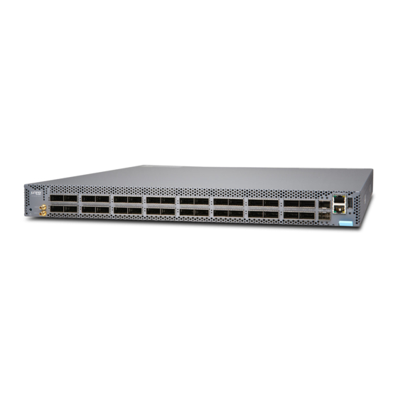
Support for high-power 400G-ZR and 400G-ZR-M optics makes this line of switches suitable for edge and Data Center Interconnect (DCI) use cases. QFX5130 Switch Description The QFX5130 line of Switches includes two compact 1-U platforms—QFX5130-32CD and QFX5130-48C. Both the switches provide high speeds, high densities, and a rich set of Junos® OS Evolved features. - Page 24 10Gbps to 400 Gbps. An Intel Xeon D-1500 processor drives the QFX5130 control plane that runs the Junos OS Evolved software and supports 32GB memory (16GBx2) of DDR4.The Junos OS Evolved software image is stored on two internal 50-GB solid-state drives (SSDs).
-
Page 25: Benefits Of The Qfx5130 Switch
• Allows current Junos OS users to seamlessly migrate to Junos OS Evolved software. With Junos OS Evolved, you can run Linux using your familiar Junos OS CLI, and run third-party Linux applications with Juniper Extension Toolkit (JET) API support, telemetry support for monitoring the DC network, and support for module-level in-service software upgrade (ISSU). -
Page 26: Qfx5130 Hardware Component Overview
QFX5130 Hardware Component Overview The QFX5130-32CD supports the components listed in Table 1 on page Table 1: QFX5130-32CD Hardware Components Component Chassis Model Juniper Model Number CLI Output Chassis QFX5130-32CD QFX5130-32CD-CHAS QFX5130-32CD n fan- n Fan module QFX5130-32CD QFX5220-32CD-FANAI (FRUs-to-... -
Page 27: System Software
FRUs airflow) System Software The Junos OS Evolved software that runs on QFX5130 Switches provides Layer 2 and Layer 3 switching, routing, and security services. Junos OS Evolved is installed on the switch solid-state drive (SSD). For more information about the features supported on the QFX5130, see Feature Explorer. -
Page 28: Qfx5130 Field-Replaceable Units
You can continue to operate the switch with just one rotor of a fan module. If more than one rotor of any fan module fails and is unable to keep the QFX5130 48C switch within desired temperature thresholds, chassis alarms occur and the QFX5130-48C switch shuts down. -
Page 29: Qfx5130 Port Panel
See "Disconnect a Fiber-Optic Cable" on page 169. NOTE: If you have a Juniper Care service contract, register any addition, change, or upgrade of hardware components at https:/ /www.juniper.net/customers/support/tools/updateinstallbase/. Failure to do so can result in significant delays if you need replacement parts. This note does not apply if you replace existing components with the same type of component. - Page 30 • 40 Gbps QSFP+ to 10 Gbps SFP+ direct attach copper breakout (DACBO) cables (40 Gbps breaks out to 10 Gbps)–Junos OS Evolved Release 20.4R1 and later. The port panel of the QFX5130-48C switch has 48 SFP56-DD 100GbE ports for server connectivity and 8 QSFP-DD 400GbE uplink ports.
- Page 31 Setting Port Speed and Channelization For QFX5130-32CD, the default speed for ports 0 through 31 is 400 Gbps. Only QSFP-DD optics inserted in these ports will link without configuration. See...
- Page 32 NOTE: The QFX5130-32CD does not support autonegotiation between devices. For QFX5130-48C, the default speed for ports 0through 47 is 100 Gbps. Only SFP56-DD optics inserted in these ports will link without configuration. The default speed for ports 48 to 55 is 400 Gbps.
- Page 33 100g user@host#set interfaces NOTE: On QFX5130 devices, there is a single FPC and PIC, which is always 0. You can channelize the port into four independent 25-Gigabit or 10-Gigabit Ethernet interfaces by configuring the number of subports and the speed. For more information, see https:/ /apps.juniper.net/...
- Page 34 LEDs for the QSFP-DD high-speed ports. Table 7 on page 27 describes how to interpret the link and activity LEDs and the status LEDs for the SFP+ ports. Table 6: QSFP-DD Network Port LEDs on a QFX5130-32CD Color State Channelized Description Unlit Off is the default mode.
- Page 35 (Continued) Table 6: QSFP-DD Network Port LEDs on a QFX5130-32CD Color State Channelized Description Flashing A 400-Gbps or 100-Gbps link is established, and there is link activity. All the channels or subports have links established, and there is link activity.
- Page 36 (Continued) Table 7: SFP+ Network Port LEDs on QFX5130-32CD Color State Description Amber Blinking Fault–The port has an interface error. QFX5130-48C Network LEDs The high-speed QSFP-DD and SFP-DD network ports use a single bi-colored LED to indicate link status, activity on the link, or a fault condition. The 10-Gbps SFP+ ports have single bi-colored LEDs that indicate link, activity, and fault conditions.
- Page 37 Table 8: QSFP-DD/SFP-DD Network Port LEDs on the QFX5130-48C Switch Color State Channelized Description Unlit Off is the default mode. The LED can be unlit even when power is present and a transceiver is present in the port. • The port is administratively disabled.
- Page 38 Anything except disabled port but no transceiver is present RELATED DOCUMENTATION Channelizing Interfaces on QFX3500, QFX3600, QFX5100, QFX10002, QFX10008, QFX10016, and EX4600 Switches QFX5130 Network Cable and Transceiver Planning | 77 Maintain Transceivers and Fiber Optic Cables on a QFX5130 Switch | 163...
-
Page 39: Qfx5130 Management Panel
QFX5130-48C Management Panel Overview | 35 QFX5130-48C Network LEDs | 38 QFX5130-32CD Management Panel Overview The management panel of the QFX5130-32CD is divided in two sections, with the port panel in between these sections. Figure 22: QFX5130-32CD Management Panel Chassis status LEDs... -
Page 40: Qfx5130-32Cd Chassis Status Leds
You can find LEDs on these management ports: Table 10 on page 32 describes the chassis status LEDs on a QFX5130-32CD, the colors and states, and the status they indicate. You can remotely view the colors of the three LEDs through the CLI by issuing the operational mode command show chassis lcd. - Page 41 CLI command. user@host> show chassis beacon fpc 0 FPC 0 The management port on a QFX5130-32CD has two LEDs—one indicates link status and the other link activity. See Figure 24 on page 34. The management port is labeled MGMT for 10/100/1000BASE-T...
- Page 42 Figure 24: Management Port LEDs on a QFX5130-32CD Switch Status LED Activity LED — — Table 11 on page 34 describes the management port LEDs. Table 11: Management Port LEDs on a QFX5130-32CD Switch Color State Description Link/Activity Unlit No link is established. There is a fault or the link is down.
-
Page 43: Qfx5130-48C Management Panel Overview
16.5 mm. For reference, SanDisk Cruzer Force, HP v207 USB drives. QFX5130-48C Chassis Status LEDs QFX5130-48C has three LEDs that indicate the system status. You can find these LEDs on the left of the small form-factor pluggable (SFP) ports. - Page 44 ID—Identification — — System status — Table 12 on page 36 describes the various states of network port LED for the SFP+ ports. Table 12: Chassis Status LEDs on a QFX5130-48C Device Name Color State Description ALM–Alarm Unlit The switch is halted or there is no alarm.
- Page 45 (Continued) Table 12: Chassis Status LEDs on a QFX5130-48C Device Name Color State Description Green Blinking The Junos OS Evolved software is getting loaded on the device. This LED is also activated when the system shutdown is in progress. Green...
-
Page 46: Qfx5130-48C Network Leds
In an unchannelized port, the port link status for the corresponding top and bottom rows is shown above the top row of ports. Figure 27: Link/Activity and Status LEDs on QFX5130-48C LEDs that indicate status and channelizationfor LEDs that indicate status and channelization for —... - Page 47 2. Green 3. Amber 4. Red Table 13: Link Activity and LED Status on QFX5130-48C Transceiver Normal Breakout Explicitly Port State Port Location Lane Display Inserted Cable Disabled Configuration State Green No Breakout Blinking green Applicable No Breakout Down Blinking red...
- Page 48 Amber port LED color is Amber The management port on a QFX5130-48C has two LEDs—one indicates link status and the other link activity. The management port is labeled MGMT for 10/100/1000BASE-T connections. See Figure 28 on page...
- Page 49 Figure 28: Management Port LEDs on a QFX5130-48C Switch Status LED Activity LED — — Table 14 on page 41describes the management port LEDs on a QFX5130-48C switch. Table 14: Management Port LEDs on a QFX5130-48C Switch Color State Description...
-
Page 50: Qfx5130 Cooling System
Do Not Install Components with Different Airflow or Wattage in the Switch | 48 The cooling system in a QFX5130 consists of six fan modules and a single fan in each power supply. The switch can ordered in one of two airflow directions: •... - Page 51 Figure 29: QFX5130-32CD Fan Module You remove and replace a fan module from the FRU end of the chassis. The QFX5130-32CD switch can work with only five fans. However, we recommend that you run the switch with all six fans for redundancy and optimal switch operation.
- Page 52 You remove and replace a fan module from the FRU end of the chassis. The QFX5130-48C switch cannot work with only five fans as the redundancy for QFX5130 48C is supported only at the rotor level. We recommend that you run with all six fans for redundancy and optimal operation of the switch.
- Page 53 (Continued) Table 15: Fan Modules in QFX5130 Switches Fan Module Airflow Diagram Label on Color of Direction of Airflow Power the Fan in the Fan Module Supplies Module Module QFX5130-48C- Figure 32 on AIR IN Juniper FRU-to-port, that is, You must...
- Page 54 Figure 31: Air-In Airflow Through QFX5130-32CD Figure 32: Air-In Airflow through QFX5130-48C...
- Page 55 Figure 33: Air-Out Airflow Through QFX5130-32CD Figure 34: Air-Out Airflow Through QFX5130-48C...
-
Page 56: Qfx5130 Fan Module Led
CAUTION: Do not mix AC and DC power supplies in the same QFX5130 chassis. However, if you need to convert a QFX5130 switch to have a different airflow, you can change the airflow pattern. To convert an AIR IN product variant to an AIR OUT product variant or an AIR OUT product variant to an AIR IN product variant, you must power off and replace all of the fans and power supplies at one time to use the new airflow direction. - Page 57 NOTE: The fans are numbered 0 through 5, starting from the fan closest to the ports. Table 16 on page 49 describes the function of the fan tray LED. Table 16: Fan Tray LED Behavior in a QFX5130 Switch Name Color...
-
Page 58: Fan Module Status
You can check the status of fan modules by issuing the show chassis temperature-thresholds, show system alarm, or show chassis environment commands, or by looking at the LEDs next to each fan module. On the QFX5130-48C switches, the LED is located on the fan module. For example: user@device> show chassis fan... - Page 59 Fan Tray 0 Fan 1 38% 11400 RPM Fan Tray 0 Fan 2 37% 12150 RPM Fan Tray 1 Fan 1 39% 11550 RPM Fan Tray 1 Fan 2 37% 12150 RPM Fan Tray 2 Fan 1 39% 11550 RPM Fan Tray 2 Fan 2 37% 12150 RPM Fan Tray 3 Fan 1...
- Page 60 12700 RPM Fan Tray 5 Fan 2 11800 RPM The QFX5130 switch has a status LED (labeled ST) for each fan module. The LED indicates the status of all the fan modules. RELATED DOCUMENTATION Maintain the QFX5130 Cooling System | 154...
-
Page 61: Qfx5130 Power System
<unit/module> that has a different airflow or wattage into the chassis. The power supplies for the QFX5130 switch are located on the FRU panel. See Figure 37 on page 53... -
Page 62: Qfx5130 Switch Ac Power Supply Modules Description
NOTE: The power supply unit requires 2-3 seconds to display the output once it is powered on. QFX5130 Switch AC Power Supply Modules Description QFX5130 switches ship with two power supplies. While QFX5130 switches can operate with the minimum number of power supplies, maximum power supplies are required to have redundancy. See Figure 39 on page 55 that depicts an example of these power supplies. -
Page 63: Qfx5130 Ac Power Specifications
Figure 39: 1600-W AC Power Supply for QFX5130 Switches An AC power supply for the QFX5130 switch is 1600 W. The power supply provides FRU-to-port or port-to-FRU airflow depending on the model and variant you purchase. The power supplies have color-coded indicators to indicate the airflow direction. -
Page 64: Ac Power Cord With Type C15 Coupler Specifications
Typical power consumption 253 W Maximum power consumption 641 W The QFX5130 AC model uses power cords with type C15 couplers. See "AC Power Cord with Type C15 Coupler Specifications" on page AC Power Cord with Type C15 Coupler Specifications Detachable AC power cords are shipped with the chassis, if you include them as part of your order. - Page 65 Table 19 on page 57 lists the AC power cord specifications provided for each country or region. Table 19: AC Power Cord Specifications Country/Region Electrical Plug Standards Juniper Spare Juniper Graphic Specifications Model Model Number Number Argentina 250 VAC, 10 A, IRAM 2073 Type RA/3 –...
- Page 66 (Continued) Table 19: AC Power Cord Specifications Country/Region Electrical Plug Standards Juniper Spare Juniper Graphic Specifications Model Model Number Number Italy 250 VAC, 10 A, CEI 23-16 Type I/3G CG_CBL- CBL-PWR- 50 Hz C15-02-IT- C15M- HITEMP-IT Japan 125 VAC, 15 A,...
-
Page 67: Qfx5130 Ac Power Supply Leds
AC input okay Fault condition — — DC output okay — Table 20 on page 59 describes the LED behavior on the QFX5130 AC power supplies. Table 20: AC Power Supply LEDs on a QFX5130 Switch Color State Description Input OK Unlit The power supply is disconnected from the power source, or there is no input from the socket. -
Page 68: Qfx5130 Dc Power Supply Description
The two power supply modules (PSMs) in QFX5130 switches are hot-removable and hot-insertable field-replaceable units (FRUs). The PSMs are preinstalled in the switch. The DC PSMs in QFX5130 switches are 1600 watt (W) with dual feeds for power resiliency. You can install replacement PSMs without powering off the switch or disrupting the switch function. - Page 69 Airflow Out (port-to-FRU) Juniper gold handle Figure 41: DC Power Supply in QFX5130 Switches CAUTION: Verify that the airflow direction on the power supply handle matches the direction of airflow in the chassis. Ensure that each power supply you install in the chassis has the same airflow direction.
-
Page 70: Qfx5130 Dc Power Specifications
"Maintain the QFX5130 Power System" on page 158. QFX5130 DC Power Specifications Table 23 on page 62 describes the DC power specifications for the DC version of QFX5130 switches. Table 23: DC Power Specifications for a QFX5130-32CD Switch Item Specifications DC Input Voltage •... -
Page 71: Qfx5130 Dc Power Supply Led
Table 24: DC Power Specifications for a QFX5130-48C Switch Item Specifications DC Input Voltage • Rated operating voltage: -48 VDC through -60 • Operating voltage range: –40 VDC through –72 DC Input Current Rating 40 A maximum Typical Power 272 W... - Page 72 Table 25: DC Power Supply LEDs on a QFX5130 Switch Color State Description Input OK Unlit The power supply is disconnected from the power source, or there is no input from the socket. Green On steadily There is DC output power from the power supply.
-
Page 73: Site Planning, Preparation, And Specifications
C HAPTER Site Planning, Preparation, and Specifications QFX5130 Site Preparation Checklist | 66 QFX5130 Site Guidelines and Requirements | 68 QFX5130 Network Cable and Transceiver Planning | 77 QFX5130 Cable Specifications and Pinouts | 86... -
Page 74: Qfx5130 Site Preparation Checklist
Power Measure the distance between — external power sources and the switch installation site. Calculate the power consumption "QFX5130 Power System" on page and requirements. Rack or Cabinet Verify that your rack or cabinet • "QFX5130 Site Guidelines and meets the minimum requirements Requirements"... - Page 75 Table 26: Site Preparation Checklist Item or Task For More Information Performed by Date Plan the rack or cabinet location, "QFX5130 Clearance Requirements including the required space for Airflow and Hardware clearances. Maintenance" on page 71 Secure the rack or cabinet to the —...
-
Page 76: Qfx5130 Site Guidelines And Requirements
QFX5130 Environmental Requirements and Specifications | 68 General Site Guidelines | 70 QFX5130 Grounding Cable and Lug Specifications | 70 QFX5130 Clearance Requirements for Airflow and Hardware Maintenance | 71 QFX5130 Chassis Physical Specifications | 73 Site Electrical Wiring Guidelines | 73... - Page 77 QFX5130-48C-AFI—At 32° F through 104° F(0° C through 40° C), there is no performance degradation up to 6000 feet (1828.8 meters). • QFX5130-32CD-AFI—At 32° F through 77° F (0° C through 25° C), there is no performance degradation up to 6000 feet (1828.8 meters). Relative humidity, operating...
-
Page 78: General Site Guidelines
The switch must be adequately grounded before power is connected to ensure proper operation and to meet safety and electromagnetic interference (EMI) requirements. You must install the QFX5130 switches in a restricted-access location and ensure that the chassis is always properly grounded. QFX5130 switches have a two-hole protective grounding terminal on the chassis. -
Page 79: Qfx5130 Clearance Requirements For Airflow And Hardware Maintenance
• The grounding cable that you provide for a QFX5130-32CD must be 14 AWG (2 mm²), minimum 60° C wire, or as permitted by the local code. • The grounding cable that you provide for a QFX5130-48C must be 6 AWG (10 mm²), minimum 90° C wire, or as permitted by the local code. - Page 80 Figure 43: Clearance Requirements for Airflow and Hardware Maintenance for a QFX5130-32CD Figure 44: Clearance Requirements for Airflow and Hardware Maintenance for a QFX5130-48C • For the cooling system to function properly, the airflow around the chassis must be unrestricted. See "QFX5130 Cooling System"...
-
Page 81: Qfx5130 Chassis Physical Specifications
• Leave at least 24 in. (61 cm) both in front of and behind the QFX5130 switch (for both QFX5130-32CD and QFX5130-48C). For service personnel to remove and install hardware components, you must leave adequate space at the front and back of the switch. -
Page 82: Qfx5130 Rack Requirements
• Electrical hazards as a result of power surges conducted over the lines into the equipment. QFX5130 Rack Requirements QFX5130 switches are designed to be installed on four-post racks. Rack requirements consist of: • Rack type • Mounting bracket hole spacing... - Page 83 Table 30 on page 75 provides the rack requirements and specifications for QFX5130 switches. Table 30: Rack Requirements for QFX5130 Switches Rack Requirement Guidelines Rack type Use a four-post rack that provides bracket holes or hole patterns spaced at 1-U (1.75 in. or 4.45 cm) increments and that meets the size and strength requirements to support the...
-
Page 84: Qfx5130 Cabinet Requirements
Secure the rack to the ceiling brackets as well as to the wall or floor brackets for maximum stability. QFX5130 Cabinet Requirements You can mount the QFX5130 switches in an enclosure or cabinet that contains a four-post 19-in. open Cabinets, Racks, Panels, and Associated Equipment (document number EIA-310-D) rack as defined in published by the Electronics Industry Association (EIA). -
Page 85: Qfx5130 Network Cable And Transceiver Planning
• The QFX5130 fans exhaust hot air either through the vents on the port panel or through the fans and power supplies. Install the switch in the cabinet in a way that maximizes the open space on the FRU side of the chassis. -
Page 86: Determining Qfx5130 Optical Interface Support
The Hardware Compatibility Tool enables you to search by product, displaying all the transceivers supported on that device, or category, by interface speed or type. The list of supported transceivers for the QFX5130 series is located at https:/ /apps.juniper.net/hct/. -
Page 87: Cable Specifications For Qsfp+, Qsfp28, And Qsfp-Dd Transceivers
• Supported operating ambient temperature range of optics for QFX5130-48C-AFI (AC) and QFX5130-48C-AFI (DC) : SDD (100G) optics with up to 5W power dissipation, QDD (400G) optics with up to 14W power dissipation supported for the entire working temperature range (40°C, 6000ft). - Page 88 Table 32: QSFP+ and QSFP28 Optical Module Receptacle Pinouts Fiber Signal Tx0 (Transmit) Tx1 (Transmit) Tx2 (Transmit) Tx3 (Transmit) Unused Unused Unused Unused Rx3 (Receive) Rx2 (Receive) Rx1 (Receive) Rx0 (Receive) Table 33: QSFP+ MPO Fiber-Optic Crossover Cable Pinouts...
-
Page 89: Understanding Qfx Series Fiber-Optic Cable Signal Loss, Attenuation, And Dispersion
Table 33: QSFP+ MPO Fiber-Optic Crossover Cable Pinouts (Continued) Understanding QFX Series Fiber-Optic Cable Signal Loss, Attenuation, and Dispersion IN THIS SECTION Signal Loss in Multimode and Single-Mode Fiber-Optic Cables | 82 Attenuation and Dispersion in Fiber-Optic Cable | 82... - Page 90 To determine the power budget and power margin needed for fiber-optic connections, you need to understand how signal loss, attenuation, and dispersion affect transmission. The QFX Series uses various types of network cables, including multimode and single-mode fiber-optic cables. Signal Loss in Multimode and Single-Mode Fiber-Optic Cables Multimode fiber is large enough in diameter to allow rays of light to reflect internally (bounce off the walls of the fiber).
-
Page 91: Calculating Power Budget And Power Margin For Fiber-Optic Cables
TIP: You can use the Hardware Compatibility Tool to find information about the pluggable transceivers supported on your Juniper Networks device. To calculate the power budget and power margin, perform the following tasks: How to Calculate Power Budget for Fiber-Optic Cables To ensure that fiber-optic connections have sufficient power for correct operation, you need to calculate the link's power budget, which is the maximum amount of power it can transmit. -
Page 92: How To Calculate Power Margin For Fiber-Optic Cables
– P The following hypothetical power budget equation uses values measured in decibels (dB) and decibels referred to one milliwatt (dBm): – P = –15 dBm – (–28 dBm) = 13 dB How to Calculate Power Margin for Fiber-Optic Cables After calculating a link's power budget, you can calculate the power margin (P ), which represents the amount of power available after subtracting attenuation or link loss (LL) from the power budget (P... - Page 93 In both examples, the calculated power margin is greater than zero, indicating that the link has sufficient power for transmission and does not exceed the maximum receiver input power. RELATED DOCUMENTATION Maintain Transceivers and Fiber Optic Cables on a QFX5130 Switch | 163...
-
Page 94: Qfx5130 Cable Specifications And Pinouts
QFX Series switch to a management device. NOTE: The QFX Series can be configured with small form-factor pluggable (SFP) management ports that support 1000BASE-SX transceivers. QFX5130 switches come with a RJ-45 management port, and support 10-Gbps speed. See the Hardware Compatibility Tool for more information about the fiber-optic cables required for use with these transceivers. -
Page 95: Rj-45 Management Port Connector Pinout Information
RJ-45 Management Port Connector Pinout Information Table 36 on page 87 provides the pinout information for the RJ-45 connector for the management port on Juniper Networks devices. Table 36: RJ-45 Management Port Connector Pinout Information Signal Description... -
Page 96: Console Port Connector Pinouts For The Qfx Series
(Continued) Table 36: RJ-45 Management Port Connector Pinout Information Signal Description TRP3+ Transmit/receive data pair 3 TRP3- Transmit/receive data pair 3 TRP2- Transmit/receive data pair 2 TRP4+ Transmit/receive data pair 4 TRP4- Transmit/receive data pair 4 Console Port Connector Pinouts for the QFX Series The console port (labeled CON or CONSOLE) is an RS-232 serial interface that uses an RJ-45 connector to connect to a console management device. -
Page 97: Qsfp-Dd Port Connector Pinout Information
• RJ-45 to USB-C adapter (JNP-CBL-RJ45-USBC) If you want to use RJ-45 to USB-A or RJ-45 to USB-C adapter you must have X64 (64-Bit) Virtual COM port (VCP) driver installed on your PC. See, https:/ /ftdichip.com/drivers/vcp- drivers/ to download the driver. Table 37: Console Port Connector Pinouts for the QFX Series Signal Description... - Page 98 (Continued) Table 38: QSFP-DD Network Port Pinout Mapping Symbol Description Ground TX4n Transmitter inverted data input TX4p Transmitter non-inverted data input Ground ModSelL Module select ResetL Module reset VCC RX +3.3V Power Supply Receiver 2-wire serial interface clock 2-wire serial interface data Ground RX3p Receiver non-inverted data output...
- Page 99 (Continued) Table 38: QSFP-DD Network Port Pinout Mapping Symbol Description Ground Ground RX2n Receiver inverted data output RX2p Receiver non-inverted data output Ground RX4n Receiver inverted data output RX4p Receiver non-inverted data output Ground ModPrsL Module Present IntL Interrupt VCC TX +3.3V power supply transmitter VCC1 +3/3V power supply...
- Page 100 (Continued) Table 38: QSFP-DD Network Port Pinout Mapping Symbol Description TX3n Transmitter inverted data input Ground TX1p Transmitter non-inverted data input TX1n Transmitter inverted data input Ground Ground TX6n Transmitter inverted data input TX6p Transmitter non-inverted data input Ground TX8n Transmitter inverted data input TX8p Transmitter non-inverted data input...
- Page 101 (Continued) Table 38: QSFP-DD Network Port Pinout Mapping Symbol Description Reserved Reserved Ground RX7p Receiver non-inverted data output RX7n Receiver inverted data output Ground RX5p Receiver non-inverted data output RX5n Receiver inverted data output Ground Ground RX6n Receiver inverted data output RX6p Receiver non-inverted data output Ground...
-
Page 102: Sfp-Dd Connector Pinout Information
(Continued) Table 38: QSFP-DD Network Port Pinout Mapping Symbol Description Ground No connect Reserved +3.3V power supply +3.3V power supply Reserved Ground TX7p Transmitter non-inverted data input TX7n Transmitter inverted data input Ground TX5p Transmitter non-inverted data input TX5n Transmitter inverted data input Ground SFP-DD Connector Pinout Information Table 39 on page 95... - Page 103 Table 39: SFP-DD Network Port Pinout Mapping Symbol Description Ground TxFault Module Fault Indication; optionally configured as legacy SFP Module Fault Indication via TWI as described in the SFP-DD TxDisable Transmitter Disable for legacy SFP channel Management I/F data line Management I/F clock Mod_ABS Module Absent...
- Page 104 (Continued) Table 39: SFP-DD Network Port Pinout Mapping Symbol Description VccT Transmitter Power Ground TD0+ Transmit Data In for legacy SFP channel TD0- Inverse Transmit Data In for legacy SFP channel Ground Ground IntL/TxFaultDD Interrupt; optionally configured as TxFaultDD via TWI as described in the SFP-DD MIS TxDisableDD Transmitter Disable for DD channel...
-
Page 105: Qsfp+, Qsfp28, And Qsfp56 Port Connector Pinout Information
(Continued) Table 39: SFP-DD Network Port Pinout Mapping Symbol Description Ground RD1- Inverse Received Data Out for DD channel RD1+ Received Data Out for DD channel Ground VccR1 Receiver Power for DD channel VccT1 Transmitter Power for DD channel Ground TD1+ Transmit Data In for DD channel TD1-... - Page 106 Table 40: QSFP+, QSFP28, and QSFP56 Port Connector Pinout Mappng Symbol Description Ground TX2n Transmitter inverted data input TX2p Transmitter non-inverted data input Ground TX4n Transmitter inverted data input TX4p Transmitter non-inverted data input Ground ModSelL Module select LPMode_Reset Low power mode reset VccRx +3.3V power supply receiver 2-wire serial interface clock...
- Page 107 (Continued) Table 40: QSFP+, QSFP28, and QSFP56 Port Connector Pinout Mappng Symbol Description Ground RX1p Receiver non-inverted data output RX1n Receiver inverted data output Ground Ground RX2n Receiver inverted data output RX2p Receiver non-inverted data output Ground RX4n Receiver inverted data output RX4p Receiver non-inverted data output Ground...
-
Page 108: Sfp, Sfp+, And Sfp28 Port Connector Pinout Information
(Continued) Table 40: QSFP+, QSFP28, and QSFP56 Port Connector Pinout Mappng Symbol Description Reserved Ground TX3p Transmitter non-inverted data input TX3n Transmitter inverted data input Ground TX1p Transmitter non-inverted data input TX1n Transmitter inverted data input Ground SFP, SFP+, and SFP28 Port Connector Pinout Information Table 41 on page 100 provides the pinout mapping for small-form factor pluggable (SFP) connectors, SFP+ connectors, and SFP28 connectors. - Page 109 (Continued) Table 41: SFP, SFP+, and SFP28 Port Connector Pinout Mapping Symbol Description TX_Disable Optical output disabled when high 2-wire serial interface data (MOD-DEF2) 2-wire serial interface data (MOD-DEF1) MOD_ABS Module absent Receiver rate select RX_LOS Receiver loss of signal indication Transmitter rate select VeeR Receiver ground...
-
Page 110: Usb Port Specifications For The Qfx Series
Transmitter ground USB Port Specifications for the QFX Series The following Juniper Networks USB flash drives have been tested and are officially supported for the USB port in the QFX Series: • RE-USB-1G-S—1-gigabyte (GB) USB flash drive (except QFX3100 Director device) •... - Page 111 NOTE: To access the pinhole reset without any hindrance, you must use a USB drive with a maximum width of 16.5 mm. For reference, SanDisk Cruzer Force, HP v207 USB drives. RELATED DOCUMENTATION Connect the QFX5130 Switch to External Devices | 146...
- Page 112 C HAPTER Initial Installation and Configuration Unpack and Mount the QFX5130 Switch | 105 Connect the QFX5130 Switch to Power | 135 Connect the QFX5130 Switch to External Devices | 146 Perform Initial Software Configuration for QFX5130 Switches | 149...
-
Page 113: Unpack And Mount The Qfx5130 Switch
Unpack a QFX5130 Switch | 105 Register Products—Mandatory to Validate SLAs | 108 Mount the QFX5130-32CD Switch in a Rack by Using the QFX5220-32CD-4PRMK Rack Mount Kit | 108 Mount the QFX5130 by Using the QFX5K-4PST-RMK-E Rack Mount Kit | 115 Unpack a QFX5130 Switch The QFX5130 chassis is a rigid sheet-metal structure that houses the hardware components. - Page 114 Table 42: Inventory of Components Supplied with a QFX5130-32CD Device Component Quantity Chassis Fan modules 6, factory installed Power supplies 2, factory installed • JPSU-1600W-1UACAFO for AC airflow out systems • JPSU-1600W-1UACAFI for AC airflow in systems Rack mount kit - QFX5K-4PST-RMK-E...
- Page 115 Table 43: Inventory of Components Supplied with a QFX5130-48C Device Component Quantity Chassis Fan modules 6, factory installed Power supplies 2, factory installed • JPSU-1600W-1UACAFO for AC airflow- out systems • JPSU-1600W-1UACAFI for AC airflow-in systems Rack mount kit - QFX5130-1RU-4PRMK...
-
Page 116: Register Products-Mandatory To Validate Slas
Register Products—Mandatory to Validate SLAs Register all new Juniper Networks hardware products and changes to an existing installed product using the Juniper Networks website to activate your hardware replacement service-level agreements (SLAs). CAUTION: Register product serial numbers on the Juniper Networks website. Update the installation base data if any addition or change to the installation base occurs or if the installation base is moved. -
Page 117: Before You Begin Rack Mounting
If you are installing the QFX5130-32CD above 60 in. (152.4 cm) from the floor, we recommend that you remove the power supplies and fan modules to minimize the... -
Page 118: Mount Qfx5130-32Cd On A Four-Post Rack Using The Qfx5220-32Cd-4Prmk Rack Mount Kit
Mount QFX5130-32CD on a Four-Post Rack Using the QFX5220-32CD-4PRMK Rack Mount Kit To mount the QFX5130-32CD on a four-post rack by using the QFX5220-32CD-4PRMK rack mount kit: Attach the ESD grounding strap to your bare wrist and to a site ESD point. - Page 119 (and cage nuts and washers if your rack requires them.) Tighten the screws. See Figure 47 on page for an example of connecting the mounting rails and blades to a QFX5130-32CD. Figure 47: Attach QFX5130-32CD to the Rack Continue to support the switch while sliding the rear-mounting blades into the channel of the side- mounting rails and securing the blades to the rack.
-
Page 120: Mount Qfx5130-32Cd On A Four-Post Cabinet
You can mount a QFX5130-32CD on four-post racks within a cabinet. For cabinet installations, you need to reconfigure the provided mounting rail. You must change the mounting rail from a flush-mount to a set-back design to allow room in the cabinet for network cabling. To mount a QFX5130-32CD on a four-post cabinet: Attach the ESD grounding strap to your bare wrist and to a site ESD point. - Page 121 51 on page 113 to understand the proper alignment for the QFX5130-32CD. Figure 51: Attach the Mounting Rails to the QFX5130-32CD Attach the mounting rail to the switch by using six M4 flat-head mounting screws (provided). Tighten the screws by using a Phillips number 2 screwdriver.
- Page 122 Figure 52 on page for an example of attaching the switch and mounting assembly to the cabinet rack. Figure 52: Attach QFX5130-32CD to Cabinet Rack 12. Continue to support the switch while sliding the rear-mounting blades into the channel of the extended mounting rails and securing the mounting blades to the rack.
-
Page 123: Mount The Qfx5130 By Using The Qfx5K-4Pst-Rmk-E Rack Mount Kit
Mount the Device by Using the QFX5K-4PST-RMK-E Rack Mount Kit On a Threaded Hole Rack | 120 Mount the Switch by Using the QFX5130-1RU-4PRMK Rack Mount Kit on a Square Hole Rack | 126 Mount Your QFX5130-48C Switch by Using the QFX5130-1RU-4PRMK Rack Mount Kit on a Threaded-Hole Four-Post Rack | 129 You can mount a QFX5130-32CD switch on a square hole or threaded hole four-post 19-in. -
Page 124: Mount The Device By Using The Qfx5K-4Pst-Rmk-E Rack Mount Kit On A Square Hole Rack
• A pair of mounting brackets • 16 flat-head M4 x 6mm Phillips screws • A pair of spacers A four-post installation evenly supports the device by all four corners. Mount the Device by Using the QFX5K-4PST-RMK-E Rack Mount Kit On a Square Hole Rack Ensure that you have the following tools and parts available: •... - Page 125 Figure 55: Front and Rear Rails Assembled 3. Attach the mounting rails to the rack. a. Standing in front of the rack, align the guide blocks of the rear mounting rails with the rear-post holes. Pull the rear mounting rails toward the front of the rack to lock the rails in place. You will hear a click sound when the latch locks into the corresponding rack holes.
- Page 126 Figure 57: Install the Front Mounting Rails c. Push the lock latch to the locked position. See Figure 58 on page 118. Figure 58: Front Mounting Rail's Lock Latch d. Visually ensure that the front and rear latches are locked into place on the mountingrails. See Figure 59 on page 119.
- Page 127 Figure 59: Mounting Rails Installed and Locked 4. Attach the spacers and the mounting brackets to the device if not pre-installed. If your device already has the spacers and mounting brackets pre-installed than skip this step and move to the next step. a.
-
Page 128: Mount The Device By Using The Qfx5K-4Pst-Rmk-E Rack Mount Kit On A Threaded Hole Rack
Figure 61: Slide the Device into the Rack 7. Tighten the two thumbscrews to secure the device. See Figure 62 on page 120. Figure 62: Tighten Thumb Screws Mount the Device by Using the QFX5K-4PST-RMK-E Rack Mount Kit On a Threaded Hole Rack Ensure that you have the following tools and parts available: •... - Page 129 • A pair of front and rear mounting rails. These mounting rails attach to the front and rear rack posts— provided with the rack mount kit • A pair of side mounting brackets and 16 flat head M4 x 6mm Phillips screws. These brackets attach to the device if not pre-installed—provided with the rack mount kit •...
- Page 130 Figure 64: Remove Guide Blocks from Rear Floating Rail c. Slide the rear floating rails into the front mounting rails. See Figure 65 on page 122. Figure 65: Slide Rear Floating Rail into Front Mounting Rail d. Mounting rails assembled. See Figure 66 on page 122.
- Page 131 hear a click sound when the latch locks into the corresponding rack holes. See Figure 67 on page 123. Figure 67: Install the Rear Floating Rails b. Move the latch lock on the front mounting rail to open position, slide the front mounting rail and position it to the front rack post.
- Page 132 c. Secure the rear floating rail to the rear rack post by using screws (not provided) appropriate for your rack threaded size. See Figure 69 on page 124. Figure 69: Secure the Rear Floating Rail d. Visually ensure that the front and rear latches are locked into place on the mounting rails. See Figure 70 on page 124.
- Page 133 a. Align the holes on the spacer and the mounting bracket with the screw holes that are on the side panel of the chassis. b. Insert the flat head M4 x 6mm Phillips screws to attach the spacer and the mounting bracket into the aligned holes on the chassis (see Figure 71 on page 125).
-
Page 134: Mount The Switch By Using The Qfx5130-1Ru-4Prmk Rack Mount Kit On A Square Hole Rack
You must attach these brackets to the device. To mount the device on four posts in a rack by using the QFX5130-1RU-4PRMK rack mount kit: 1. Wrap and fasten the ESD grounding strap to your bare wrist, and connect the other end of the strap to the ESD point on the device. - Page 135 Figure 74: Assemble the Mounting Rails b. The mounting rails are assembled. See Figure 75 on page 127. Figure 75: Front and Rear Rails Assembled 3. Attach the mounting rails to the rack. a. Standing in front of the rack, align the guide blocks of the rear-mounting rails with the rear-post holes.
- Page 136 Move the latch lock on the front-mounting rail to open position, slide the front- mounting rail, and insert the guide blocks into the front rack posts. See Figure 77 on page 128. Figure 77: Attach the QFX5130-48C Chassis to the Rack c. Push the lock latch to the locked position. See Figure 78 on page 129.
-
Page 137: Mount Your Qfx5130-48C Switch By Using The Qfx5130-1Ru-4Prmk Rack Mount Kit On A Threaded-Hole Four-Post Rack
Mount Your QFX5130-48C Switch by Using the QFX5130-1RU-4PRMK Rack Mount Kit on a Threaded-Hole Four-Post Rack You can mount the QFX5130-48C switch in a four-post rack or a cabinet. Ensure that you have the following tools and parts available: • An ESD grounding strap (not provided) •... - Page 138 Figure 79: Attach the Side-Mounting Brackets 4. You can also flush mount the chassis on the rear side. Figure 80: Flush Mount the Chassis from Rear Side 5. Assemble the mounting rails: a. Remove the guide blocks from the front-mounting rails by loosening the screws and washers. Retain the guide blocks, screws, and washers for later use.
- Page 139 Figure 81: Remove the Guide Blocks from the Front Mounting Rail b. Remove the guide blocks from the rear-mounting rail by loosening the screws and washers. Retain the guide blocks, screws, and washers for later use. Figure 82: Remove the Guide Blocks from the Rear-Mounting Rail c.
- Page 140 a. Insert the guide pin of the rear-mounting rails into the rear-post holes. Pull the rear-mounting rails toward the front of the rack to lock the rails in place. You will hear a distinct click sound when the latch locks into place. Figure 84: Install the Rear-Mounting Rails b.
- Page 141 Figure 86: Secure the Rear-Mounting Brackets d. Visually ensure that the front and rear latches are locked into place on the mounting rails. The mounting rails must be securely installed on the rack. Figure 87: Mounting Rails Installed and Secured 7.
- Page 142 Figure 88: Slide the Device into the Rack 8. Tighten the two thumbscrews to secure the device. Figure 89: Tighten the Thumbscrews RELATED DOCUMENTATION Rack-Mounting and Cabinet-Mounting Warnings Connect the QFX5130 Switch to Power | 135...
-
Page 143: Connect The Qfx5130 Switch To Power
QFX5130 switch to earth ground before you connect it to power. You must install QFX5130 switches in a restricted-access location and ensure that the chassis is always properly grounded. QFX5130 switches come with a two-hole protective grounding terminal provided on the chassis. - Page 144 • Grounding cable: • QFX5130-32CD: The grounding cable must be 14 AWG (2 mm²), minimum 90° C wire, or as permitted by the local code. • QFX5130-48C: The grounding cable must be 14 AWG (2 mm²), minimum 90° C wire, or as permitted by the local code.
-
Page 145: Ground The Qfx5130-48C Switch
Figure 90: Connect a Grounding Cable to a QFX5130-32CD 2. Connect the remaining end of the grounding cable to a proper earth ground, such as the rack in which the switch is mounted. 3. Dress the grounding cable and ensure that it does not touch or block access to other device components and that it does not drape where people could trip over it. -
Page 146: Connect Ac Power To A Qfx5130 Switch
7. Figure 91: Ground the QFX5130-48C Switch 8. Dress the grounding cable. Ensure that the cable doesn’t block access to or come in contact with other device components. Also, ensure that the cable doesn’t drape where people could trip over it. - Page 147 "Install an AC Power Supply Unit in QFX5130 Switches" on page 161. The QFX5130 switch ships from the factory with two power supplies. Each power supply is a hot- removable and hot-insertable field-replaceable unit (FRU). You can install a replacement power supply in the slots next to the fan modules without powering off the switch or disrupting the switching function.
-
Page 148: Connect Dc Power To A Qfx5130 Switch
Connect DC Power to a QFX5130 Switch IN THIS SECTION Before You Begin | 140 Connect DC Power to a QFX5130 Switch | 141 Before You Begin Before you connect DC power to the switch:... -
Page 149: Connect Dc Power To A Qfx5130 Switch
• Ring lug - KST P/N: RNYBS8-4 or equivalent (not provided) Connect DC Power to a QFX5130 Switch To connect DC power to the DC model of a QFX5130 Switch: Attach the grounding strap to your bare wrist and to a site ESD point on the switch. - Page 150 • The cable with very high resistance (indicating an open circuit) to chassis ground is negative (–) and will be installed on the V– (input) DC power input terminal. CAUTION: You must ensure that power connections maintain proper polarity. The power source cables might be labeled (+) and (–) to indicate their polarity.
- Page 151 0 V and that the cable leads do not become active when you connect DC power. The QFX5130 switch should connect the power supplies to an external DC power source or a -0% to +20% tolerance DC mains, supplied with an NRTL-approved circuit breaker rated at 40-A.
- Page 152 Figure 94: Remove Terminal Block Cover Remove the screws on the terminals by using the screwdriver. Save the screws. See Figure 95 on page 144. Figure 95: QFX5130 Faceplate Not used Release latch — — Handle V– terminal — —...
- Page 153 Figure 96: Secure Ring Lugs to the Terminals on the QFX5130 DC Power Supply The QFX5130 Switch operates with a DC power supply that has a single, non-redundant feed input. For source redundancy, you must install two DC power supplies in the QFX5130 Switch—...
-
Page 154: Connect The Qfx5130 Switch To External Devices
11. Verify that the IN and OUT LEDs on the power supply are lit green and are on steadily. RELATED DOCUMENTATION QFX5130 Power System | 53 Connect the QFX5130 Switch to External Devices IN THIS SECTION Connect a Device to a Network for Out-of-Band Management | 146 Connect a Device to a Management Console Using an RJ‑45 Connector | 147... -
Page 155: Connect A Device To A Management Console Using An Rj-45 Connector
To connect a device to a network for out-of-band management (see Figure 98 on page 147): 1. Connect one end of the Ethernet cable to the management port on the device. 2. Connect the other end of the Ethernet cable to the management device. Figure 98: Connect a Device to a Network for Out-of-Band Management Connect a Device to a Management Console Using an RJ‑45 Connector Ensure that you have an Ethernet cable that has an RJ-45 connector at either end and an RJ-45-to-DB-9... - Page 156 • RJ-45 to DB-9 adapter (JNP-CBL-RJ45-DB9) • RJ-45 to USB-A adapter (JNP-CBL-RJ45-USBA) • RJ-45 to USB-C adapter (JNP-CBL-RJ45-USBC) If you want to use RJ-45 to USB-A or RJ-45 to USB-C adapter you must have X64 (64-Bit) Virtual COM port (VCP) driver installed on your PC. See, https:/ /ftdichip.com/drivers/vcp- drivers/ to download the driver.
-
Page 157: Perform Initial Software Configuration For Qfx5130 Switches
• Stop Bits—1 • DCD State—Disregard You must perform the initial configuration of the QFX5130 switch through the console port by using the CLI or through zero-touch provisioning (ZTP). To use ZTP to provision the device, you must have access to a Dynamic Host Control Protocol (DHCP) server, an anonymous FTP, HTTP, or a Trivial File Transfer Protocol (TFTP) server on which the software image and configuration files are stored. - Page 158 To connect and configure the switch from the console: Connect the console port to a laptop or a PC by using an RJ-45 cable and an RJ-45 to DB-9 adapter. The console (CON) port is located on the top-right corner of the port panel. Log in as root.
- Page 159 NOTE: On the QFX5130-32CD switch, the management port re0:mgmt-0 is the bottom RJ-45 port on the right side of the port panel and is labeled MGMT. On the QFX5130-48C switch, the management port re0:mgmt-0 is located on the rear panel towards left hand side and the port on top is the management port, and is labeled MGMT.
- Page 160 NOTE: When Telnet is enabled, you cannot log in to a QFX5130 switch through Telnet by using root credentials. Root login is allowed only for SSH access. 11. Enable SSH service for root login. [edit] root@# set system services ssh root-login allow 12.
- Page 161 C HAPTER Maintaining Components Maintain the QFX5130 Cooling System | 154 Maintain the QFX5130 Power System | 158 Maintain Transceivers and Fiber Optic Cables on a QFX5130 Switch | 163 Power Off a QFX5130 Switch | 172...
-
Page 162: Maintain The Qfx5130 Cooling System
(ESD) damage (see Prevention of Electrostatic Discharge Damage). Ensure that you have the following parts and tools available to remove a fan module from a QFX5130 switch: • ESD grounding strap • Antistatic bag or an antistatic mat 1. - Page 163 NOTE: The fan modules on the QFX5130 are hot-swappable and hot-removable field- replaceable units (FRUs). During replacement of a fan module while the switch is online, you must replace one fan module at a time.
-
Page 164: Install A Fan Module In Qfx5130 Switches
Install a Fan Module in QFX5130 Switches Before you install a fan module in a QFX5130 switch, ensure that you have taken the necessary precautions to prevent electrostatic discharge (ESD) damage (see Prevention of Electrostatic Discharge Damage). - Page 165 The fan modules are designed so that they can only be inserted into the QFX5130-32CD product variant that supports the same airflow type. See"QFX5130 Power System" on page 53 for more information.
-
Page 166: Maintain The Qfx5130 Power System
(ESD) damage (see Prevention of Electrostatic Discharge Damage). Ensure that you have the following parts and tools available to remove a power supply from a QFX5130 switch: • ESD grounding strap • Antistatic bag or an antistatic mat 1. - Page 167 NOTE: If only one power supply is installed in your QFX5130 switch, you must power off the switch before removing the power supply. See "Power Off a QFX5130 Switch" on page 172. 3. Disconnect power to the switch: • AC power supply—If the AC power source outlet has a power switch, set it to the OFF (O) position.
- Page 168 Figure 107: Remove an AC Power Supply Unit from a QFX5130-48C Switch Figure 108: Remove a DC Power Supply Unit from a QFX5130-32CD Switch Figure 109: Remove a DC Power Supply Unit from a QFX5130-48C Switch...
-
Page 169: Install An Ac Power Supply Unit In Qfx5130 Switches
9. Replace with another power supply module. Install an AC Power Supply Unit in QFX5130 Switches • Before you install a power supply in QFX5130 switches, ensure that you have taken the necessary precautions to prevent electrostatic discharge (ESD) damage (see... - Page 170 Figure 111: Install an AC Power Supply Unit in a QFX5130-48C Switch NOTE: You must connect each power supply to a dedicated power source outlet. NOTE: If you have a Juniper Care service contract, register any addition, change, or upgrade of hardware components at https:/ /www.juniper.net/customers/support/tools/updateinstallbase/.
-
Page 171: Maintain Transceivers And Fiber Optic Cables On A Qfx5130 Switch
• Rubber safety caps to cover the transceiver and fiber-optic cable connector • A dust cover to cover the port or a replacement transceiver The transceivers for Juniper Networks devices are hot-removable and hot-insertable field-replaceable units (FRUs). You can remove and replace the transceivers without powering off the device or disrupting... - Page 172 NOTE: After you remove a transceiver, or when you change the media-type configuration, wait for 6 seconds for the interface to display the operational commands. Figure 112 on page 165 shows how to remove a QSFP+ transceiver. The procedure is the same for all types of transceivers except the QSFP28 and CFP transceivers.
- Page 173 CAUTION: Do not bend the fiber-optic cable beyond its minimum bend radius. An arc smaller than a few inches in diameter can damage the cable and cause problems that are difficult to diagnose. 6. To remove an SFP56-DD, SFP, SFP+, XFP, a QSFP+, or QSFP56-DD transceiver: a.
-
Page 174: Install A Transceiver
Juniper Networks. If you face a problem running a Juniper device that uses third-party optical modules or cables, JTAC may help you diagnose host-related issues if the observed issue is not, in the opinion of JTAC, related to the use of the third-party optical modules or cables. - Page 175 ZR or ZR+) can potentially cause thermal damage to or reduce the lifespan of the host equipment. Any damage to the host equipment due to the use of third-party optical modules or cables is the users’ responsibility. Juniper Networks will accept no liability for any damage caused due to such use.
- Page 176 NOTE: Make sure to use a dust cap to cover ports that are unused. NOTE: While using Finisar AOC SFP+ optical module with the QFX5130-48C switch, you may need to pull the module upwards to pull out the module smoothly from the cage.
-
Page 177: Disconnect A Fiber-Optic Cable
• A rubber safety cap to cover the transceiver • A rubber safety cap to cover the fiber-optic cable connector Juniper Networks devices have optical transceivers to which you can connect fiber-optic cables. To disconnect a fiber-optic cable from an optical transceiver installed in the device: 1. -
Page 178: Connect A Fiber-Optic Cable
LASER WARNING: Do not look directly into a fiber-optic transceiver or into the ends of fiber-optic cables. Fiber-optic transceivers and fiber-optic cables connected to transceivers emit laser light that can damage your eyes. 2. Carefully unplug the fiber-optic cable connector from the transceiver. 3. -
Page 179: How To Handle Fiber-Optic Cables
How to Handle Fiber-Optic Cables Fiber-optic cables connect to optical transceivers that are installed in Juniper Networks devices. Follow these guidelines when handling fiber-optic cables: • When you unplug a fiber-optic cable from a transceiver, place rubber safety caps over the transceiver and on the end of the cable. -
Page 180: Power Off A Qfx5130 Switch
• Ensure that you do not need to forward traffic through the switch. NOTE: Use the following procedure to turn off power on a QFX5130 switch. Ensure that you have the following parts and tools available to power off the switch: •... - Page 181 • Connect a management device to the console (CON) port on a QFX5130 switch. For instructions about connecting a management device to the console (CON) port, see "Connect a Device to a Management Console Using an RJ‑45 Connector" on page 147.
- Page 182 RELATED DOCUMENTATION Connect the QFX5130 Switch to Power | 135...
-
Page 183: Troubleshooting Hardware
C HAPTER Troubleshooting Hardware Troubleshoot the QFX5130 Switch | 176... -
Page 184: Troubleshoot The Qfx5130 Switch
Panel" on page • JTAC If you need assistance during troubleshooting, you can contact the Juniper Networks Technical Assistance Center (JTAC) by using the Web or by telephone. If you encounter software problems, or problems with hardware components not discussed here, contact JTAC. -
Page 185: Qfx5130 Alarm Messages Overview
QFX5130 Alarm Messages Overview When a QFX5130 switch detects an alarm condition, it lights the red or yellow alarm LED on the management panel as appropriate. To view a more detailed description of the alarm cause, issue the show system alarms operational CLI command. -
Page 186: Chassis Alarm Messages
Table 44 on page 178 describes the chassis alarm messages on the QFX5130 switches. Junos OS Evolved systems, such as QFX5130-32CD and QFX5130-48C, are based on a new alarm infrastructure, not all power supplies and fan alarms are supported. Table 44 on page 178 shows these alarms. - Page 187 Table 44: Chassis Alarm Messages for QFX5130 Switches (QFX5130-32CD and QFX5130-48C) (Continued) Component Alarm Type CLI Message Recommended Action sensor-location Temp Sensor Too Check the environmental conditions and alarms on the other devices. Ensure that the environmental factors (such as hot...
- Page 188 Table 44: Chassis Alarm Messages for QFX5130 Switches (QFX5130-32CD and QFX5130-48C) (Continued) Component Alarm Type CLI Message Recommended Action Minor (yellow) FPC 0 Temperature Warm Check environmental conditions and alarms on other devices. Ensure that environmental factors (such as hot air blowing around the equipment) do not affect the temperature sensor.
-
Page 189: Contacting Customer Support And Returning The Chassis Or Components
C HAPTER Contacting Customer Support and Returning the Chassis or Components Contact Customer Support to Obtain Return Material Authorization | 182 Return a QFX5130 Chassis or Components | 183... -
Page 190: Contact Customer Support To Obtain Return Material Authorization
Contact Customer Support to Obtain Return Material Authorization If you need to return a device or hardware component to Juniper Networks for repair or replacement, obtain a Return Material Authorization (RMA) number from Juniper Networks Technical Assistance Center (JTAC). You must obtain an RMA number before you attempt to return the component. -
Page 191: Return A Qfx5130 Chassis Or Components
Locate the Serial Number ID Labels on FRUs in a QFX5130 Switch | 188 If you are need to return a switch or component to Juniper Networks for repair or replacement, you must locate the serial number of the switch or component. You must provide this serial number to the Juniper Networks Technical Assistance Center (JTAC) when you contact them to obtain a Return Materials Authorization (RMA). -
Page 192: List The Chassis And Component Details Using The Cli
To list the switch and components and their serial numbers, use the show chassis hardware CLI operational mode command. The following outputs list the switch components and serial numbers for QFX5130-32CD and QFX5130-48C switches. user@device> show chassis hardware Hardware inventory:... - Page 193 Xcvr 33 REV 01 740-030658 AD1125A04M8 SFP+-10G-USR Fan Tray 0 QFX5130-32CD Fan Tray, Front to Back Airflow - AFO Fan Tray 1 QFX5130-32CD Fan Tray, Front to Back Airflow - AFO Fan Tray 2 QFX5130-32CD Fan Tray, Front to Back...
- Page 194 1W2CZ7A53402R QSFP56-DD-400GBASE-DR4 Xcvr 55 REV 01 740-085351 1W2CZ7A54500A QSFP56-DD-400GBASE-DR4 Xcvr 57 REV 01 740-030658 1A1MWGA7506HN SFP+-10G-USR Fan Tray 0 QFX5130-48C/CM Fan Tray, Front to Back Airflow - AFO Fan Tray 1 QFX5130-48C/CM Fan Tray, Front to Back Airflow - AFO...
-
Page 195: Locate The Chassis Serial Number Id Label On A Qfx5130 Switch
QFX5130-32CD port panel. See Figure 115 on page 187 for the QFX5130-32CD. The chassis serial number for QFX5130-48C is located on the top panel. See Figure 116 on page 188. -
Page 196: Locate The Serial Number Id Labels On Frus In A Qfx5130 Switch
• • AC Power supply—The serial number ID label is on the top of the AC power supply. Figure 117 on page 189 shows the location of the serial number ID label on the AC power supply for QFX5130 switches. - Page 197 Figure 117: Serial Number ID Label on a QFX5130 AC Power Supply • Fan module—The serial number ID label is on the bottom of the fan module for QFX5130-32CD switches. Figure 118 on page 189 shows the location of serial number on QFX5130-32CD switches.
-
Page 198: Remove The Solid-State Drives For Rma On Qfx5130-32Cd Switches
The QFX5130-32CD switches have two solid-state drives (SSDs) that store the software images, system logs, and the configuration files. Before returning a chassis to Juniper Networks as part of a Return Merchandise Authorization (RMA), you have the option of removing the SSDs and disposing them according to your own company’s security procedures. - Page 199 Figure 120: Remove Screws on SSD Doors for a QFX5130-32CD Switch Remove the doors and set aside the screws. Use the Phillips screwdriver to remove the screw on one of the SSDs and set it aside. Figure 121: Removing the Screw and Lifting the SDD Out Lift the end furthest from the connector and remove from the cavity.
-
Page 200: Remove The Solid-State Drives For Rma On A Qfx5130-48C Switch
The QFX5130-48C switches have two solid-state drives (SSDs) that store the software images, system logs, and the configuration files. Before returning a chassis to Juniper Networks as part of a Return Merchandise Authorization (RMA), you have the option of removing the SSDs and disposing them according to your own company’s security procedures. - Page 201 Figure 124 on page 193 Figure 124: Removing the Screw and Lifting the SDD Out of a QFX5130-48C Switch Lift the end furthest from the connector and remove from the cavity. Replace screws and hand-tighten them using the Phillips screwdriver.
-
Page 202: How To Return A Hardware Component To Juniper Networks, Inc
NOTE: Do not return any component to Juniper Networks, Inc. unless you have first obtained an RMA number. Juniper Networks, Inc. reserves the right to refuse shipments that do not have an RMA. -
Page 203: Guidelines For Packing Hardware Components For Shipment
Pack a QFX5130 Switch for Shipping | 196 Pack QFX5130 Components for Shipping | 197 If you are returning a QFX5130 or one of its components to Juniper Networks for repair or replacement, pack the item as described in this topic. -
Page 204: Pack A Qfx5130 Switch For Shipping
"Power Off a QFX5130 Switch" on page 172. Remove the cables that connect the QFX5130 switch to all external devices. Remove all field-replaceable units (FRUs) from the switch. Have one person support the weight of the switch while another person unscrews and removes the mounting screws. -
Page 205: Pack Qfx5130 Components For Shipping
CAUTION: Do not stack switch components. Return individual components in separate boxes if they do not fit together on one level in the shipping box. To pack and ship QFX5130 components: • Place individual FRUs in antistatic bags. • Ensure that the components are adequately protected with packing materials and packed so that the pieces are prevented from moving around inside the carton. -
Page 206: Safety And Compliance Information
C HAPTER Safety and Compliance Information Safety Information | 199 Compliance Statements for NEBS | 199 Compliance Statements for EMC Requirements | 199 Compliance Standards for QFX5130 Switches | 201... -
Page 207: Safety Information
Networks products. Follow the guidelines provided in the guide to reduce the likelihood of personal injury, equipment damage, and damage to surrounding areas. Along with the information provided in the Juniper Networks Safety Guide, you must read and understand the QFX5240 specific safety information provided in this hardware guide. - Page 208 Canada CAN ICES-3 (A)/NMB-3(A) European Community This is a Class A product. In a domestic environment, this product might cause radio interference in which case the user might be required to take adequate measures. Israel Translation from Hebrew—Warning: This product is Class A. In residential environments, the product might cause radio interference, and in such a situation, the user might be required to take adequate measures.
-
Page 209: Compliance Standards For Qfx5130 Switches
Compliance Standards for QFX5130 Switches IN THIS SECTION Compliance Statement for Argentina | 203 The QFX5130 switches comply with the following standards: • Safety • IEC 60950-1:2005, AMD1:2009, AMD2:2013 Information Technology Equipment – Safety (Include all country deviation). - Page 210 • IEC/EN 60825-1 Safety of Laser Products – Part 1: Equipment classification and requirements • EMC • FCC 47 CFR Part 15 • ICES-003 / ICES-GEN • BS EN 55032 • BS EN 55035 • EN 300 386 V1.6.1 • EN 300 386 V2.2.1 •...
- Page 211 Compliance Statement for Argentina EQUIPO DE USO IDÓNEO.
Need help?
Do you have a question about the QFX5130 and is the answer not in the manual?
Questions and answers