
Subscribe to Our Youtube Channel
Related Manuals for Studer SCore Live


Summary of Contents for Studer SCore Live
- Page 1 Studer SCore Live (For Vista and OnAir 3000 Systems) Product Information (January 2010, 4 Edition)
- Page 2 Copyright by Studer Professional Audio GmbH Studer Professional Audio GmbH Printed in Switzerland Technical Documentation Order no. BD10.275160-4 (Ed. 0110) Althardstrasse 30 CH-8105 Regensdorf – Switzerland http://www.studer.ch Subject to change Studer is a registered trade mark of Studer Professional Audio GmbH, Regensdorf...
- Page 3 Safety Information Safety Information CAUTION To reduce the risk of electric shock, do not remove covers. No user-ser- RISK OF ELECTRIC SHOCK DO NOT OPEN viceable parts inside. Refer servicing to qualifi ed service personnel (i.e., ATTENTION persons having appropriate technical training and experience necessary RISQUE DE CHOC ELECTRIQUE NE PAS OUVRIR to be aware of hazards to which they are exposed in performing a repair...
- Page 4 Installation General Installation Instructions Please consider besides these general instructions also any product-specifi c instructions in the “Installation” chapter of this manual. Unpacking Check the equipment for any transport damage. If the unit is mechanically damaged, if liquids have been spilled or if objects have fallen into the unit, it must not be connected to the AC power outlet, or it must be immediately disconnected by unplugging the power cable.
- Page 5 Installation / EMC Class I Equipment (Mains Operation) Should the equipment be delivered without a matching mains cable, the latter has to be prepared by a trained person using the attached female plug (IEC 320 / C13 or IEC 320 / C19) with respect to the applicable regulations in your country.
- Page 6 EMC / Maintenance / ESD • Use a system grounding concept that satisfi es the safety requirements (class I equipment must be connected with a protective ground conduc- tor) and that also takes into consideration the EMC require ments. When deciding between radial, surface, or combined grounding, the advantages and disadvantages should be carefully evaluated in each case.
- Page 7 ESD / Repair • When performing a repair by replacing complete assemblies, the removed assembly must be sent back to the supplier in the same packing material in which the replacement assembly was shipped. If this should not be the case, any claim for a possible refund will be null and void.
- Page 8 Repair / Disposal SMD Components Studer has no commercially available SMD components in stock for ser- vice purposes. For repair, the corresponding devices have to be purchased locally. The specifi cations of special components can be found in the service manual.
- Page 9 Any changes or modifi cations not expressly approved by the manufacturer could void the user’s authority to operate the equipment. Also refer to relevant information in this manual. CE Declaration of Conformity Studer Professional Audio GmbH, CH-8105 Regensdorf, declare under our sole responsibility that the product Studer SCore Live (from serial no.
- Page 10 Beyond these specifi cations, possible problems are described below. Ambient Temperature Units and systems by Studer are generally designed for an ambient tempera- ture range (i.e. temperature of the incoming air) of +5 °C to +40 °C. When rack mounting the units, the intended air fl ow and herewith adequate cooling must be provided.
- Page 11 Appendix evaporation (sublimation) may be expected; otherwise the system must be heated and dried while switched off. A system without visible internal formation of ice or condensation should be heated up with its own heat dissipation, as homogeneously (and subsequently as slow) as possible;...
- Page 12 Appendix Appendix 2: Mains Connector Strain Relief For anchoring connectors without a mechanical lock (e.g. IEC mains connec- tors), we recommend the following arrangement: Procedure: The cable clamp shipped with your unit is auto-adhesive. For mounting please follow the rules below: •...
- Page 13 The following Terms and Conditions grant the right to use all programs of Studer that are part of the System and/or its options at the time of its delivery to the Customer, as well as the installation software on the original data disk and the accompanying documentation (“License Material”).
- Page 14 Reverse engineering is only permitted with the express consent of Studer. The consent of Studer can be obtained but is not limited to the case in which the interface software can not be provided by Studer. In any case Studer has to be informed immediately upon complete or partial reverse engineering.
-
Page 15: Table Of Contents
Adjustments, Repair, Cleaning ..........................1-3 Introduction ..................................2-1 Block Diagram ................................2-2 The Frame and its Cards .............................2-2 Additional Information ...............................2-3 SCore Live Modules ................................3-1 SCore Live Host Card ..............................3-2 SCore Live/Pro DSP Card............................3-5 Bridge Card .................................3-7 3.3.1 Bridge Card IP Address Setting .........................3-9 3.3.2 Bridge Card IP Address Recovery ........................3-9... -
Page 16: General
SCore Live GENERAL Utilization for the Purpose Intended The SCore Live system is intended for professional use. It is presumed that the unit is operated only by trained personnel. Servicing is reserved to skilled technicians. The electrical connections may be connected only to the voltages and signals designated in this manual. - Page 17 SCore Live Ventilation Implementation A power dissipation estimation, considering the number of cards and their confi guration within the frame, is strongly recommended. The following tables give some guidelines. Power Dissipation Card No. Card Name/Description (approx.) Backplane with power supply...
-
Page 18: Adjustments, Repair, Cleaning
The primary fuse is located within the power supply module and cannot be changed. In case of failure, the complete power supply unit must be replaced. Please ask your nearest Studer representative. Cleaning: Do not use any liquids to clean the exterior of the unit. A soft, dry cloth or brush will usually do. -
Page 19: Introduction
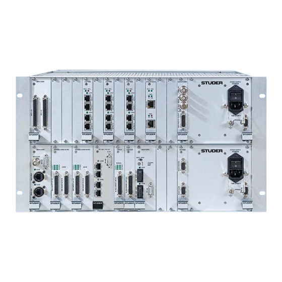
SCore Live INTRODUCTION The SCore Live system occupies just 6U rack space and provides space for up to nine DSP cards. It also holds up to twelve D21m I/O cards of various formats in addition to one ( ) or two ( ) D21m gene- ral-purpose input/output (GPIO) card(s). -
Page 20: Block Diagram
Audio In/Out I/O Slot: 10 11 12 As illustrated above, an SCore Live frame houses up to nine DSP cards in the center of the upper frame section. It also holds up to two ( ) or one ) additional D21m GPIO card(s) at the left of the DSP cards. -
Page 21: Additional Information
SCore Live Additional Information Control Signal Flow: HD Link Desk EXT. BRIDGE SYNC GPIO CARD GPIO CARD DSP CARD DSP CARD DSP CARD DSP CARD PRIMARY PSU CARD CARD 24 V SCoreLive BACKPLANE TDM Bus Sync Bus System Clock Bus... -
Page 22: Score Live Modules
SCore Live SCore Live MODULES SCore Live Modules Name Order No. Host Card 1.943.326 DSP Pro Card 1.943.360 Bridge Card 1.943.370 Ext. Sync Card 1.943.331 Primary Power Supply DB15 1.943.304 Air Defl ection/Filter Unit 1.949.599 Fan Unit 1 U 1.949.597... -
Page 23: Score Live Host Card
SCore Live SCore Live Host Card 1.943.326 The Host card is the logical link between the Bridge card and the OnAir 3000 desk. It hosts the DNet mix engine control software. The backplane connector provides 5 V power to the card. The card can be hot-swapped, but requires a power off/on cycle in order to correctly initialize the DSP cards. - Page 24 SCore Live STATUS LEDs: During power-up of the core, the Host card STATUS LEDs are controlled by the embedded controller. After the operating system has successfully started and initialized, the application (e.g. OnAir 3000) is taking over the control over the LED bar.
- Page 25 SCore Live Application Status Regardless of the settings of the DIP switches on the Host card the applica- tion is taking over the LED bar after successful initialization of the OS and indicates the following: Reserved for future use; always off Reserved for future use;...
-
Page 26: Score Live/Pro Dsp Card
SCore Live/Pro DSP Card 1.943.360 The SCore Live/Pro DSP card is used in the SCore Live for digital audio processing. The VDCA TDM bus interface allows the card to interchange audio data, serial data, and program code with the bridge card and other DSP cards. - Page 27 SCore Live S2 Default Setting: IDLE FAIL LEDs: IDLE / FAIL Card is ready and waiting for code Card is processing Card has detected an error and is disconnected from the TDM Bus Card is booting code (HD) LOCK Indicates a valid HD link signal at the corresponding input.
-
Page 28: Bridge Card
Bridge Card 1.943.370 The SCore Bridge card is used in the SCore Live to manage the whole core system. Two Gigabit Ethernet connectors provide a redundant connection to the desk or host application. The card downloads code to the DSP cards and passes serial data, parameters, and meter data between the desk or host application and the DSP cards. - Page 29 OFF. IP Address ( When replacing a Bridge card in an SCore Live of an OnAir 3000 system, copy the IP address of the old card (can be found in the DSP.ini file) to the new card using Internet Explorer. Otherwise the system will not be operative.
-
Page 30: Bridge Card Ip Address Setting
The default IP address of the primary port is 192.168.1.60, of the secondary port 192.168.2.60. • Select “core management”, password: “studer”. • Select “View/Change IP addresses confi guration”. For OnAir3000 consoles, the IP address of Ethernet port 1 is usually set according to the following rules: IP address = 192.168.SID.15... -
Page 31: Reset The Web If Password To Default
Connect to port 1 of the Bridge card using FTP User name = root Password = Obelix Open the folder /Studer/www/CGI-DATE/ Delete the existing password fi le: manager_passwd Now you can login on the Bridge card’s web interface using the default pass- word (studer). -
Page 32: Ext. Sync Card
Three inputs (VIDEO IN, WCLK IN, and AES SYNC IN) can be used; their signals are sent to the SCore Live sync bus on the backplane. While the video sync is separated on the card, the other signals are just driven onto the bus. - Page 33 SCore Live EXT LOCK LED: Indicates that the applied external sync is used by the system. Setting DIP Switch: VIDEO IN termination (default setting OFF: High-Z / ON: 75 Ω) reserved (default setting OFF) reserved (default setting OFF) WCLK IN termination (default setting OFF: High-Z / ON: 75 Ω)
-
Page 34: Primary Power Supply
Air Deflector/Filter Unit 1.949.599 If the power dissipation of an SCore Live frame is between 50 and 100 W, air deflector/filter units must be used on top of and below the frame. For a frame dissipating more power, a fan unit (see below) must be used at the bottom of the frame, combined with an air deflector/filter unit on its top. -
Page 35: D21M I/O Subsystem
A 15-pin D-type cable (order no. 89.20.1167) for connection to the primary PSU is required. Please note that currently the fan monitoring is implemented for the use of the fan unit within the SCore Live only. For more information on cooling as well as guidelines for power dissipation estimation refer to chapter 1.2.2, paragraph “thermal considerations”.
Need help?
Do you have a question about the SCore Live and is the answer not in the manual?
Questions and answers