Table of Contents
Advertisement
Quick Links
USER MANUAL
CT1000 v2
CT1000 v2 with Tamper
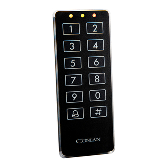
CT1000 v2 is a touch keypad that can be installed and used for
many different purposes, e.g. to open a door, turn on the light, or
call for an elevator - just a few among many other options.
Art.no. 460100 - CT1000v2 Black
Art.no. 460106 - CT1000v2 White.
Art.no. 460100T - CT1000 v2 with Tamper Black.
Art.no. 460106T - CT1000 v2 with Tamper White.
www.conlan.eu
USER MANUAL:
CT1000 v2
CT1000 v2 WITH TAMPER
CONLAN ApS publications may not be reproduced in any form or by any means without written permission from the copyright owner
Publications of CONLAN ApS are protected by copyright and all rights are reserved.
Advertisement
Table of Contents

Related Manuals for Salto 460100T


Summary of Contents for Salto 460100T
- Page 1 - just a few among many other options. Art.no. 460100 - CT1000v2 Black Art.no. 460106 - CT1000v2 White. Art.no. 460100T - CT1000 v2 with Tamper Black. Art.no. 460106T - CT1000 v2 with Tamper White. www.conlan.eu USER MANUAL:...
-
Page 2: Table Of Contents
CONTENT 1. INSTALLATION Page 3 2. ACCESS Page 3 2.1. Using the device Page 3 3. FIXED USER PIN CODES MANAGEMENT Page 4 3.1 Add user PIN codes Page 5 3.2 Delete user codes Page 5 4. CONFIGURATION Page 6 4.1 Software Factory Reset Page 6 4.2 Delete All User PIN Codes... -
Page 3: Installation
1. INSTALLATION To learn how to install the keypad, please refer to the installation guide. 2. ACCESS The keypad is a standalone device that allows access to open a lock by entering a custom user PIN code. 2.1. Using the device The CT1000 v2 can store up to 200 fixed PIN codes that range from 1 to 8 digits long. -
Page 4: Fixed User Pin Codes Management
Wrong Code Example: When a wrong code is entered, a rejection beep will sound, and the red LED will blink three times. If four successive wrong attempts are made, the keypad will lock out for 60 seconds. 3. FIXED USER PIN CODES MANAGEMENT Each user code is stored in a specific address of internal memory (from 1 to 200). -
Page 5: Add User Pin Codes
3.1 Add user PIN codes Insert: The yellow LED will blink rapidly. Then insert a user position between 1 and 200 to place the new PIN code. Example: When a valid position is entered, the yellow LED will blink slowly while the green LED will blink rapidly until a new user PIN code is inserted. -
Page 6: Configuration
4. CONFIGURATION To configure the CT1000 v2, you need to access the Service Configuration Menu with the Service Configuration Code (12347890 as factory default). This code is used to authenticate and access the menu. You can access this menu within the first 5 minutes after the device has been powered up, after which it becomes inaccessible. -
Page 7: Delete All User Pin Codes
4.2 Delete All User PIN Codes To clear all stored user PIN codes from the device’s memory, please follow these steps: Insert: A confirmation beep will sound to indicate that all the stored PIN codes have been deleted. The keypad will return to the Service Configuration Menu and will be ready to perform another action. -
Page 8: Change Service Configuration Code
4.4 Change Service Configuration Code Insert: The green LED will blink slowly. The keypad is ready to receive a new Service Configuration Code. Insert a code that is between 4 to 8 digits. Example: The green LED will blink slowly while the yellow LED will blink rapidly until the new Service Configuration Code is inserted again to confirm the action. -
Page 9: Idle State Indication
4.5.1 Idle State Indication Is the device normal state, it remains idle until a user action is performed. Insert: The device shows the current Idle State indication. The yellow LED ON as default. 4.5.2 Output2 Active State Indication This will show when OUTPTU2 is active (regardless of whether it’s floating or GND as output signal) by a right user PIN code inserted or a REX input triggered for example. -
Page 10: Back Lights Configuration
4.5.4 Back Lights Configuration Insert: The device turns OFF all indication LED’s and shows the current Back Lights State. As default the Back Lights are turned ON for 5 seconds when a key is touched, after what the lights turns OFF again. This state is indicated by a slow blink of the Back Lights. -
Page 11: Outputs Configuration
4.6 Outputs Configuration For Output 1 Insert: The yellow LED will blink slowly for Output1. For Output 2 Insert: The yellow and red LED’s will blink slowly for Output2. The device’s outputs can be configured with the following parameters: 1. Normal Mode: In this mode, the output is floating in idle state and grounded when active. 2. - Page 12 Insert: For Normal Mode Insert: For Inverted Mode An activation time must be set. The yellow LED blinks to indicate time configuration. Insert time in hours (between 0 to 12) to activate the correspondent output. Insert: To confirm. The yellow LED will blink slowly and the green LED will blink fast, indicating that the device is waiting for a time in minutes , insert a time between 0 and 60.
-
Page 13: Feedback
4.7 Feedback This function allows changing the exBuzzer input behavior to use it as a Feedback input. When the configured input is Active, it will switch to an Inactive state once the Feedback input is triggered (grounded). This feature is particularly useful when using a sensor to detect if a door is open or locked. After the user enters a valid PIN, the output is activated to grant access and the door can be opened. - Page 14 Insert: For Output 1 For Output 2 Insert: The green LED will blink rapidly to indicate that a trigger flank needs to be configured. Insert: For High to Low Flank For Low to High Flank Insert: To save the changes. The device returns to the Service Insert: Configuration menu, and another configuration can be performed.
-
Page 15: Special Functions
4.8 Special Functions You can enable or disable four special functions: 1. Mute: To turn ON/OFF the device’s sound. 2. Service Code Timeout: By default ON, it means you can only use the Service Configuration Code within the first 5 minutes after powering up. When this option is turned OFF, the Service Configuration Code will work anytime. -
Page 16: Splitter And Bell Function
4.9 Splitter and Bell Function The device, as default, is configured to activate Output2 (yellow wire) every time a valid code is inserted. Besides, the Output1 (white wire) is activated every time the Bell Key is pushed. To change this default behavior: Enter: The yellow and green LED’s will light solid until a Splitter value position is inserted. - Page 17 Splitter 5 ..Disabled Output1 Output2 The keypad go back to User Configuration Menu and is ready to perform another action. All user Enter: PIN codes from 1 to 4 activates Output1 and all user PIN codes from 6 to 200 activates Output2 1 and 200 are considered “special values”.
-
Page 18: Custom User Output
4.10 Custom User Output It’s possible to customize the output and its behavior for specific users. In this menu, you can as- sign a custom output to a specific user, that can be different from the default output signed by the Splitter. -
Page 19: Hardware Factory Reset
5. HARDWARE FACTORY RESET If you need to reset the device to its factory default settings, please follow these steps: 1. Disconnect the Power Supply, ensure the device is not powered. Power +VDC Supply -GND Power +VDC Supply -GND 2. Connect the REX (blue wire) with the exBuzzer (brown wire). -
Page 20: Rex Input
REX input becomes a critical elements to the system behavior. 7. TAMPER BUTTON (Only for Art.no. 460100T and Art.no. 460106T ) The tamper button is a normally open (NO) switch located on the back of the device. It is directly connected to two cables that interface with an alarm system. -
Page 21: Technical Specifications
8. TECHNICAL SPECIFICATIONS Device measures: 50.3 mm x 130.3 mm x 8 mm 9 to 24 VDC (12VDC Recommended) Power source: Power consumption on Idle: 3.96 mA at 12VDC Inputs: exGreen, exRed, exBuzzer and REX [Active LOW (-/GND)] Outputs: Output1 and Output2, Open Collector [Active LOW (-/GND)] Protection rate: IP67 Environmental conditions:...
Need help?
Do you have a question about the 460100T and is the answer not in the manual?
Questions and answers