Table of Contents
Advertisement
Quick Links
Instruction Manual
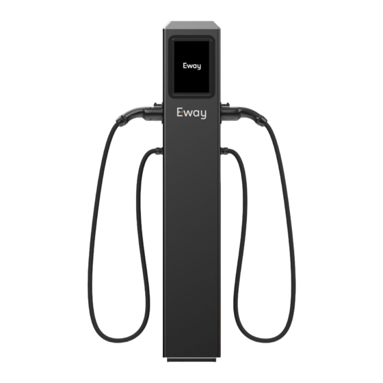
AC Charging Station 2x22kW
Copyright Eway S.A., Warsaw, Poland | Document version: 1.0.3 | Number of pages: 31 | Issue date: 17.05.2024 r.
This document is subject to change with product development. |The manufacturer does not guarantee the
accuracy of the data contained in this document. | This documentation has been prepared by the manufacturer
of the device, Nordgrid Sp. z o.o., Warsaw, under the exclusive jurisdiction of Eway S.A., Warsaw.
Advertisement
Table of Contents

Summary of Contents for e-way Pillar with cable
- Page 1 Instruction Manual AC Charging Station 2x22kW Copyright Eway S.A., Warsaw, Poland | Document version: 1.0.3 | Number of pages: 31 | Issue date: 17.05.2024 r. This document is subject to change with product development. |The manufacturer does not guarantee the accuracy of the data contained in this document.
-
Page 2: Table Of Contents
Table of contents 1. General information ........................3 5. Description of start-up, operation and shut-down operations ......11 Charging instructions ......................11 Copyright ............................3 Waiver of liability ........................3 6. Maintenance and disposal ....................13 Storage and transport ........................3 Cleaning and care (maintenance) ................13 Description of the device and its purpose .............3 Disposal and environmental protection (meeting the requirements of environmental legislation) ............13 Name and information plate ......................4... -
Page 3: General Information
1. General information Copyright Description of the device and its purpose Eway owns its trademarks and has the exclusive right to use them for The Eway Charging Station is a device designed for charging electric commercial, advertising and promotional purposes. Eway's trademark or hybrid vehicles using cashless payment, without external applications. -
Page 4: Name And Information Plate
Name and information plate Explanation of basic concepts The nameplate is located on the outer wall of the Charging Station - within the meaning of Article 2. point 27. of the Act appliance. It contains key information about the on Electromobility and Alternative Fuels (i.e. - Journal of Laws of 2019, appliance, viz: item 1124, as amended) is an infrastructure enabling the use of Charging Services, including in particular facilities for charging electric or hybrid... -
Page 5: Explanation Of Symbols On The Rating Plate
Explanation of symbols on the rating plate Before commissioning, read the Attention, electrical appliance Grounded device operating instructions The packaging and the device are Ban on disposing of waste electrical Symbol of the manufacturer's made of recyclable materials and electronic equipment in declaration, the product placed municipal waste bins on the market complies with the... -
Page 6: User Safety
2. User safety Occupational health and safety/ General information Specify how to meet the requirements of health Use of the Charging Station by persons who are intoxicated or under the influence of drugs and by persons under the age of 18 and safety legislation. -
Page 7: Conditions For Safe Operation Of The Appliance And Warnings Of Dangers Arising From Improper Use
Fire protection In the event of a fire at the Charging Station, switch off the power as soon as possible, then disconnect the vehicle and, if possible, move the vehicle Fire protection in accordance with the Act of 24 August 1991 on fire to a safe distance. -
Page 8: User Interface And Description Of Devices Indicating Status And Availability Of The Charging Point
3. User interface and description of devices indicating status and availability of the Charging Point General information Touchscreen The User Interface consists of the following elements: The touchscreen allows the user to interact directly with the device. It is used to operate the Charging Station application. Figure 4 shows its 1. -
Page 9: Led Strips
LED strips Payment card reader LED strips, located on the sides of the Station, above the handles of the The payment card reader is located in the bottom left corner of the Charging Connectors, indicate the current status and availability of the touchscreen (Figure 5.). -
Page 10: Available Charging Modes
4. Available charging modes The Charging Station has 4 charging modes (Fig. 5.) : 1. Unlimited charging 2. Charging on time 3. Charging for energy 4. Charging for an amount Unlimited charging Charging for energy In this mode, charging is terminated The vehicle is charged by specifying the by the vehicle when the battery is fully amount of energy the vehicle will be... -
Page 11: Description Of Start-Up, Operation And Shut-Down Operations
5. Description of start-up, operation and shut-down operations Charging instructions Follow the steps indicated to start charging the vehicle: Press the button in the central part of the start-up screen (Fig. 4, item no. 4). On the "Select Charging Channel" screen, check that the Station has an available Charging Point. - Page 12 Once the charging process is complete, a parking charge is applied until the vehicle is disconnected from the Charging Station. The following information is displayed on the screen (fig. 15.): • current parking fee, • the current standstill time since the end of charging, •...
-
Page 13: Maintenance And Disposal
6. Maintenance and disposal Once every six months it is recommended to carry out a visual inspection Disposal and environmental protection of the housing and an external inspection of the components and (meeting the requirements of environmental legislation) accessories, and once a year a detailed inspection of all the components Do not dispose of electrical and electronic equipment with normal contained in the unit by an authorised person. -
Page 14: Testing And Operation Of Charging Stations
7. Testing and operation of Charging Stations Service, repair and replacement of components and parts - service manual A service inspection of the Charging Station should be carried out once a year. Mechanical components such as sockets, charging cables, plugs, handles and plug holders only require a surface check. -
Page 15: Electrical Testing Of The Charging Station - Description Of How To Check The Condition Of The Equipment, Including Safety Components
The Charge Station components may only be replaced when the power Charging cable with Type 2 plug - unscrew the cable gland, supply is switched off and by authorised personnel. Replacement of unhook the cables from the terminal strip located on the side inside components and subassemblies must be carried out in accordance with the station. -
Page 16: Continuity Measurement Of Protective Conductors
Continuity measurement of protective conductors The open circuit measurement voltage should be between 4 and 24 V (AC or DC). The continuity measurement is to be performed with a current greater than or equal to 200 mA. The required measurement accuracy is The continuity of the protective conductors to be better than 30 %. -
Page 17: Measurement Of The Resistance Of The Working Earths
Standardised cut-off time values for differential current equal to [ms]. Type 2I n 4I n 10I n 5;10;20;50;100;200 [A] Switch-off time [ms] Figure 25. Measurement of resistance Figure 26. Measurement between the protective between live conductors L1-L2 conductor connected to the earthing system and live conductors Table 2 Standardised cut-off time values for RCD type B table data obtained from the UDT website Based on the standard: PN-HD 60364-6:2016-07 Based on standards: PN-EN 61008-1:2013-05,... -
Page 18: Functional Tests Of The Charging Station And Security Elements
The test should be carried out with a meter, with a suitable attachment, The standard applies to type F and type B residual current allowing measurement in a circuit with an overcurrent circuit breaker circuit breakers with and without integral overcurrent PN-EN 62423:2013-06 without tripping the breaker with the function of measuring the short protection for domestic and similar use... -
Page 19: Term Of Servicing
Errors in terms of damage to the device and incorrect voltage or current The operation of the Charging Station is considered to be correct when it correctly undergoes the charging process described in section no. 5 and parameters are regarded as critical errors. If these occur, the device will automatically abort the charging process or not start the charging reacts appropriately to charging errors described in section no. - Page 20 Error name „Self-healing” procedure Result Error name „Self-healing” procedure Result -Interrupting charging or -Charging interruption, preventing it from starting, -reset of the respective -reset of the respective Abort loading. Completion of Charging Point in the controller, Abort loading. Completion of CP communication Charging Point in the controller, the transaction and return to...
-
Page 21: Technical Data
9. Technical data Charging station parameters Mechanical parameters Type of station Connector type Type 2 Material Acid-resistant steel/plastic Number of Charging Points Cable type Spiral/straight Charging point power up to 22 kW Colours EWAY/RAL/ On request Dimensions (H x W x D) [mm]. 1500 x 260 x 260 Operating temperature From -10°C to + 40°C...
Need help?
Do you have a question about the Pillar with cable and is the answer not in the manual?
Questions and answers