
Subscribe to Our Youtube Channel
Related Manuals for Motorola solutions Mag One BPR 50dX


Summary of Contents for Motorola solutions Mag One BPR 50dX
- Page 1 DIGITAL TWO-WAY RADIO Mag One BPR 50dX Portable Radio User Guide *MN010575A01* FEBRUARY 2024 MN010575A01-AA © 2024 Motorola Solutions, Inc. All Rights Reserved.
-
Page 2: Table Of Contents
MN010575A01-AA Contents Contents Legal and Support....................... 4 Intellectual Property and Regulatory Notices...................4 Legal and Compliance Statements......................5 Supplier's Declaration of Conformity..................... 5 Important Safety Information......................6 Notice to Users (FCC)........................6 Notice to Users (ISED)........................6 Chapter 1: Read Me First..................... 7 Chapter 2: Radio Overview....................8 2.1 Programmable Buttons........................9 2.1.1 Assignable Radio Function.................... - Page 3 MN010575A01-AA Contents Chapter 8: Authorized Accessories List................23...
-
Page 4: Legal And Support
License Rights The purchase of Motorola Solutions products shall not be deemed to grant either directly or by implication, estoppel or otherwise, any license under the copyrights, patents or patent applications of Motorola Solutions, except for the normal nonexclusive, royalty-free license to use that arises by operation of law in the sale of a product. -
Page 5: Legal And Compliance Statements
MN010575A01-AA Legal and Support © 2024 Motorola Solutions, Inc. All Rights Reserved Legal and Compliance Statements Supplier's Declaration of Conformity Supplier's Declaration of Conformity Per FCC CFR 47 Part 2 Section 2.1077(a) Responsible Party Name: Motorola Solutions, Inc. Address: 2000 Progress Pkwy, Schaumburg, IL. 60196... -
Page 6: Important Safety Information
RF energy awareness, and control for compliance with applicable standards and regulations. Any modification to this device, not expressly authorized by Motorola Solutions, may void the user's authority to operate this device. Under Innovation, Science, and Economic Development Canada (ISED) regulations, this radio transmitter may only operate using an antenna of a type and maximum (or lesser) gain approved for the transmitter by Innovation, Science, and Economic Development Canada (ISED). -
Page 7: Chapter 1: Read Me First
MN010575A01-AA Chapter 1: Read Me First Chapter 1 Read Me First This user guide covers the basic operations of your radios. Notations Used in This Manual Throughout the text in this publication, you notice the use of Warning, Caution, and Notice. These notations are used to emphasize that safety hazards exist, and the care that must be taken or observed. -
Page 8: Chapter 2: Radio Overview
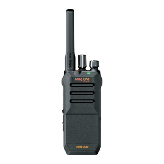
MN010575A01-AA Chapter 2: Radio Overview Chapter 2 Radio Overview Figure 1: Radio Overview Action Description Antenna Channel Selector Knob On/Off/Volume Control Knob LED Indicator Emergency Button Push-to-Talk (PTT) Button Side Button 1 Side Button 2 Microphone Speaker Programming Port Accessory Connector... -
Page 9: Programmable Buttons
MN010575A01-AA Chapter 2: Radio Overview Programmable Buttons Depending on the duration of a button press, the programmable buttons function differently. Table 1: Button Press Duration Action Description Press Press and release. Long press Press and hold for one second or longer depending on the settings through the Customer Programming Software (CPS). -
Page 10: Chapter 3: Radio Led Indications
MN010575A01-AA Chapter 3: Radio LED Indications Chapter 3 Radio LED Indications The LED Indicator shows the operational status of your radio. A qualified technician can permanently disable the LED indication by preprogramming it. Table 3: LED Indication Indication Status Solid Red The radio is transmitting. -
Page 11: Chapter 4: Getting Started
MN010575A01-AA Chapter 4: Getting Started Chapter 4 Getting Started This chapter provides instructions on how to prepare your radio for use. Charging the Battery Your radio is powered by a Lithium-Ion (Li-Ion) battery. Prerequisites: Turn off your radio when charging. Procedure: ●... -
Page 12: Removing The Battery
MN010575A01-AA Chapter 4: Getting Started 2. Press the battery firmly and slide upwards till the latch snaps into place. Removing the Battery Procedure: 1. Turn off your radio. 2. Flip the battery latch open. -
Page 13: Attaching The Antenna
MN010575A01-AA Chapter 4: Getting Started 3. Slide the battery out of the battery compartment and lift it. Attaching the Antenna Procedure: 1. Set the antenna in the receptacle. 2. Turn the antenna clockwise. -
Page 14: Removing The Antenna
MN010575A01-AA Chapter 4: Getting Started NOTE: Fastening the antenna blocks water and dust from entering the radio. Removing the Antenna Procedure: 1. Turn the antenna counterclockwise. 2. Remove the antenna from the receptacle. -
Page 15: Attaching The Belt Clip
MN010575A01-AA Chapter 4: Getting Started Attaching the Belt Clip Procedure: Align the grooves on the clip with the grooves on the battery and press it downwards until it clicks. Removing the Belt Clip Procedure: 1. To remove the clip, press the belt clip tab away from the battery. 2. -
Page 16: Attaching The Universal Connector Cover
MN010575A01-AA Chapter 4: Getting Started Attaching the Universal Connector Cover When and where to use: Replace the universal connector cover or dust cover when the universal connector is not in use. Procedure: 1. Insert the slanted end of the cover into the slots above the universal connector. 2. -
Page 17: Turning The Radio On
MN010575A01-AA Chapter 4: Getting Started 4.10 Turning the Radio On Procedure: Turn the On/Off/Volume knob clockwise until a click sounds. Result: If your radio is turned on, your radio shows the following indications: ● A tone sounds. NOTE: If the Tones/Alerts function is disabled, no tone sounds. ●... -
Page 18: Chapter 5: Time-Out Timer
MN010575A01-AA Chapter 5: Time-Out Timer Chapter 5 Time-Out Timer Your system administrator can set the time-out time for a channel through the Customer Programming Software (CPS). Before the preset timeout timer of the radio expires, a continuous warning beep is emitted based on the preset timeout warning timer time. -
Page 19: Chapter 6: Selecting Channels
MN010575A01-AA Chapter 6: Selecting Channels Chapter 6 Selecting Channels Your radio supports up to 64 channels. Each channel can be programmed with different features that support different groups of users. The radio supports up to four zones, each with 16 channels. Procedure: Select channels by toggling the Channel Selector knob. -
Page 20: Chapter 7: Calls
MN010575A01-AA Chapter 7: Calls Chapter 7 Calls Depending on the type of call, you can make, receive, and respond to calls in both Conventional Analog and Digital mode. Group Calls Group Calls are calls from an individual radio to a group of radios. To communicate in a group, your radio must first be configured as a part of the talkgroup. -
Page 21: Making Private Calls
MN010575A01-AA Chapter 7: Calls 7.2.1 Making Private Calls Procedure: 1. To select a channel with an active subscriber ID, toggle the Channel Selector knob. 2. To call, press the PTT button. 3. Wait for the Talk Permit Tone to end, and speak into the microphone. NOTE: If the selected channel is busy, a busy tone sounds and your radio unable to make a call. - Page 22 MN010575A01-AA Chapter 7: Calls 3. Wait for the Talk Permit Tone to end, and speak into the microphone.
- Page 23 MN010575A01-AA Chapter 8: Authorized Accessories List Chapter 8 Authorized Accessories List Table 4: Antennas Part Number Description AN000468A01 Mag One UHF Whip Antenna (400- 470 MHz) AN000462A01 Mag One UHF Stubby Antenna (450 - 470 MHz) AN000463A01 Mag One UHF Whip Antenna (450 - 527 MHz) AN000464A01 Mag One VHF Whip Antenna (136 - 155 MHz) AN000465A01...
- Page 24 MN010575A01-AA Chapter 8: Authorized Accessories List Table 10: Remote Speaker Microphone Part Number Description PMMN4092_ Mag One Remote Speaker Microphone Table 11: Power Supplies and Charging Cables Part Number Description PS000150A31 United States Adapter USB-A Detachable PS000150A32 Europe Adapter USB-A Detachable PS000150A35 Argentina Adapter USB-A Detachable PS000150A36...
- Page 25 MN010575A01-AA Table des matières Table des matières Avis juridique et soutien..................... 4 Propriété intellectuelle et avis réglementaires..................4 Déclarations juridiques et de conformité....................5 Déclaration de conformité du fournisseur..................5 Information sur la sécurité importante...................6 Avis aux utilisateurs (FCC)......................7 Avis aux utilisateurs (ISED)......................7 Chapitre 1 : Lisez-moi d’abord...................
- Page 26 MN010575A01-AA Table des matières Chapitre 8 : Liste des accessoires approuvés..............25...
-
Page 27: Avis Juridique Et Soutien
à Motorola Solutions, autres que la licence habituelle d’utilisation non exclusive et libre de droit qui découle légalement de la vente du produit. -
Page 28: Déclarations Juridiques Et De Conformité
MN010575A01-AA Avis juridique et soutien dépendre des caractéristiques d’une unité mobile d’abonné ou d’une configuration de certains paramètres. Contactez votre représentant Motorola Solutions pour en savoir plus. © 2024 Motorola Solutions, Inc. All Rights Reserved Déclarations juridiques et de conformité... -
Page 29: Information Sur La Sécurité Importante
Cet émetteur radio a été approuvé par Innovation, Sciences et Développement économique Canada (ISDE) pour utilisation avec une antenne approuvée par Motorola Solutions offrant le gain maximal autorisé et l’impédance requise pour le type d’antenne indiqué. Il est strictement interdit d’utiliser avec cet appareil tout type d’antenne ne figurant pas dans cette liste et présentant un gain supérieur au maximum indiqué... -
Page 30: Avis Aux Utilisateurs (Fcc)
Avis aux utilisateurs (ISED) Le fonctionnement de votre radio Motorola Solutions est assujetti à la Loi sur la radiocommunication et doit se conformer aux règles et règlements du ministère Innovation, Sciences et Développement économique Canada (ISED) du gouvernement fédéral. ISDE exige que les utilisateurs de fréquences mobiles terrestres... -
Page 31: Chapitre 1: Lisez-Moi D'abord
MN010575A01-AA Chapitre 1: Lisez-moi d’abord Chapitre 1 Lisez-moi d’abord Le présent guide d’utilisation porte sur le fonctionnement de base de votre radio. Notations utilisées dans le manuel En parcourant le texte de ce document, vous remarquerez l’utilisation des mots Avertissement, Mise en garde et Remarque. -
Page 32: Chapitre 2: Présentation De La Radio
MN010575A01-AA Chapitre 2: Présentation de la radio Chapitre 2 Présentation de la radio Figure 1 : Présentation de la radio Action Description Antenne Bouton de sélection de canal Bouton Marche/Arrêt/Volume Voyant DEL Bouton Urgence Touche Presser pour Parler (PTT) Touche latérale 1 Touche latérale 2 Microphone Haut-parleur... -
Page 33: Touches Programmables
MN010575A01-AA Chapitre 2: Présentation de la radio Touches programmables Selon la durée de la pression, les boutons programmables fonctionnent différemment. Tableau 1 : Durée de pression Action Description Appuyer Appuyer et relâcher. Appui long Appuyez et maintenez pendant une seconde ou plus selon les paramètres du logiciel de programmation client (CPS). -
Page 34: Chapitre 3: Voyants Del De La Radio
MN010575A01-AA Chapitre 3: Voyants DEL de la radio Chapitre 3 Voyants DEL de la radio Le voyant DEL indique l’état de fonctionnement de la radio. Un technicien qualifié peut désactiver de façon permanente le voyant DEL en le préprogrammant. Tableau 3 : Voyant DEL Indication État Rouge fixe... -
Page 35: Chapitre 4: Pour Commencer
MN010575A01-AA Chapitre 4: Pour commencer Chapitre 4 Pour commencer Ce chapitre fournit des instructions pour préparer votre radio en vue de son utilisation. Charge de la batterie Votre radio est alimentée par une batterie au lithium-ion. Préalables : Éteignez votre radio durant la charge. Procédure : ●... -
Page 36: Installation De La Batterie
MN010575A01-AA Chapitre 4: Pour commencer Installation de la batterie Procédure : 1. Glissez la batterie dans le logement de la batterie. 2. Appuyez fermement sur la batterie et faites glisser le loquet vers le haut jusqu’à ce qu’il s’enclenche. Retrait de la batterie Procédure : 1. -
Page 37: Installation De L'antenne
MN010575A01-AA Chapitre 4: Pour commencer 2. Rabattez le loquet de la batterie pour l’ouvrir. 3. Faites glisser la batterie hors de son compartiment et soulevez-la. Installation de l’antenne Procédure : 1. Placez l’antenne dans son orifice. 2. Tournez l’antenne dans le sens horaire. -
Page 38: Retrait De L'antenne
MN010575A01-AA Chapitre 4: Pour commencer REMARQUE : Fixer l’antenne empêche l’eau et la poussière d’entrer dans la radio. Retrait de l’antenne Procédure : 1. Tournez l’antenne dans le sens antihoraire. 2. Retirez l’antenne de son orifice. -
Page 39: Fixation De La Pince De Ceinture
MN010575A01-AA Chapitre 4: Pour commencer Fixation de la pince de ceinture Procédure : Alignez les encoches de la pince avec celles de la batterie et poussez vers le bas, jusqu’à ce que vous entendiez un déclic. Retrait de la pince de ceinture Procédure : 1. -
Page 40: Installation Du Couvercle Du Connecteur Universel
MN010575A01-AA Chapitre 4: Pour commencer Installation du couvercle du connecteur universel Où et quand utiliser : Replacez le connecteur universel ou le couvercle antipoussière lorsque le connecteur universel n’est pas en service. Procédure : 1. Insérez l’extrémité inclinée du couvercle dans les rainures correspondantes en haut du connecteur universel. -
Page 41: Retrait Du Couvercle Du Connecteur Universel
MN010575A01-AA Chapitre 4: Pour commencer Retrait du couvercle du connecteur universel Procédure : Retirez le couvercle du connecteur universel ou le couvercle antipoussière en tirant sur le couvercle. Exigences subséquentes : Replacez le couvercle antipoussière lorsque le connecteur universel n’est pas en service. 4.10 Allumer la radio Procédure :... -
Page 42: Réglage Du Volume
MN010575A01-AA Chapitre 4: Pour commencer 4.12 Réglage du volume Procédure : Pour régler le volume de votre radio, effectuez l’une des actions suivantes : ● Pour augmenter le volume, tournez le bouton Marche/Arrêt/Volume dans le sens horaire. ● Pour réduire le volume, tournez le bouton Marche/Arrêt/Volume dans le sens antihoraire. REMARQUE : Vous pouvez programmer un écart de volume minimal afin d’empêcher le réglage du volume à... -
Page 43: Chapitre 5: Minuterie De Délai D'attente
MN010575A01-AA Chapitre 5: Minuterie de délai d’attente Chapitre 5 Minuterie de délai d’attente Votre administrateur système peut définir le délai d’attente d’un canal via le logiciel de programmation client (CPS). Avant l’expiration du délai d’attente prédéfini de la radio, une courte tonalité d’avertissement est émise en fonction du délai d’attente prédéfini. -
Page 44: Chapitre 6: Sélection Des Canaux
MN010575A01-AA Chapitre 6: Sélection des canaux Chapitre 6 Sélection des canaux Votre radio prend en charge jusqu’à 64 canaux. Chaque canal peut être programmé avec différentes fonctions pour divers groupes d’utilisateurs. La radio prend en charge jusqu’à 4 zones, chacune avec 16 canaux. -
Page 45: Chapitre 7: Appels
MN010575A01-AA Chapitre 7: Appels Chapitre 7 Appels Selon le type d’appel, vous pouvez faire et recevoir des appels et y répondre en mode conventionnel analogique et numérique. Appels de groupe Les appels de groupe sont des appels d’une radio individuelle à un groupe de radios. Pour communiquer dans un groupe, votre radio doit avoir été... -
Page 46: Réponse À Des Appels Privés
MN010575A01-AA Chapitre 7: Appels 7.2.1 Appels privés Procédure : 1. Pour sélectionner un canal avec un ID d’abonné actif, tournez le bouton de sélection de canaux. 2. Pour faire un appel, appuyez sur le bouton PTT. 3. Attendez la fin de la tonalité d’autorisation de parler et parlez dans le microphone. REMARQUE : Si le canal sélectionné... -
Page 47: Appel Général
MN010575A01-AA Chapitre 7: Appels 7.3.1 Appel général Procédure : 1. Pour sélectionner un canal avec un ID de groupe actif, tournez le bouton de sélection de canaux. 2. Pour faire un appel, appuyez sur le bouton PTT. 3. Attendez la fin de la tonalité d’autorisation de parler et parlez dans le microphone. - Page 48 MN010575A01-AA Chapitre 8: Liste des accessoires approuvés Chapitre 8 Liste des accessoires approuvés Tableau 4 : Antennes Numéro de pièce Description AN000468A01 Antenne fouet UHF Mag One (400 à 470 MHz) AN000462A01 Antenne tronquée UHF Mag One (450 à 470 MHz) AN000463A01 Antenne fouet UHF Mag One (450 à...
- Page 49 MN010575A01-AA Chapitre 8: Liste des accessoires approuvés Numéro de pièce Description PMLN6536_ 2 fils avec tube transparent, noir Tableau 10 : Haut-parleur/microphone à distance Numéro de pièce Description PMMN4092_ Haut-parleur/microphone à distance Mag One Tableau 11 : Blocs d’alimentation et câbles de chargement Numéro de pièce Description PS000150A31...
Need help?
Do you have a question about the Mag One BPR 50dX and is the answer not in the manual?
Questions and answers