
Related Manuals for Kverneland Visus


Summary of Contents for Kverneland Visus
- Page 1 – x 1000 ha RPM Visus Operating manual Edition 02.2015 Printing 03.2015 Language EN [Original] For software from 1.05 Reference number AC753751...
- Page 2 Tel. +49 (0) 2921/974-0 Copyright by Kverneland Group Soest GmbH, Germany. Reproduction, transfer to other media, translation or the use of extracts or parts of this manual without the explicit permission of Kverneland, is not permitted. All rights reserved. The contents of this operating manual are subject to...
-
Page 3: Table Of Contents
Table of contents Table of contents Preliminary information ......Safety Instruction Other applicable documents Symbols Safety ............Familiarising yourself with the device ..Range of application Characteristics An overview of the device Technical data Functions Delivery and assembly ......Assembly Connecting .......... -
Page 4: Preliminary Information
Preliminary information Target group Preliminary information This operating manual is intended for trained farmers and individuals who are otherwise qualified to perform agricultural activities and who have received instruction in the operation of this machine. Safety Study the contents of this operating manual carefully, which are rele- vant for your activity, before initial operation or assembly of the ma- chine. -
Page 5: Symbols
Preliminary information Symbols In order to make this manual clear and easy to read, we have used various symbols. They are explained below: • A bullet point accompanies each item in a list A triangle indicates operating functions which must be performed →... -
Page 6: Safety
Safety Safety Check the cables Check cables before connecting them and replace damaged cables. Damaged cables can result in damage to the machine or cause un- controlled behaviour in the electronic control system. Observe the temperature range The device will only operate reliably within the specified temperature range. -
Page 7: Familiarising Yourself With The Device
Familiarising yourself with the device Familiarising yourself with the device This chapter contains general information on your machine and infor- mation on: • Range of application • Characteristics • Technical data • Functions Range of applica- The device is designed for use in agriculture. It controls agricultural machinery and devices. -
Page 8: Characteristics
Familiarising yourself with the device Characteristics Control and monitoring are possible using a terminal in connection with further components on the respective machine which can be matched to the type of machine being used. The overall system consists of the components: •... -
Page 9: An Overview Of The Device
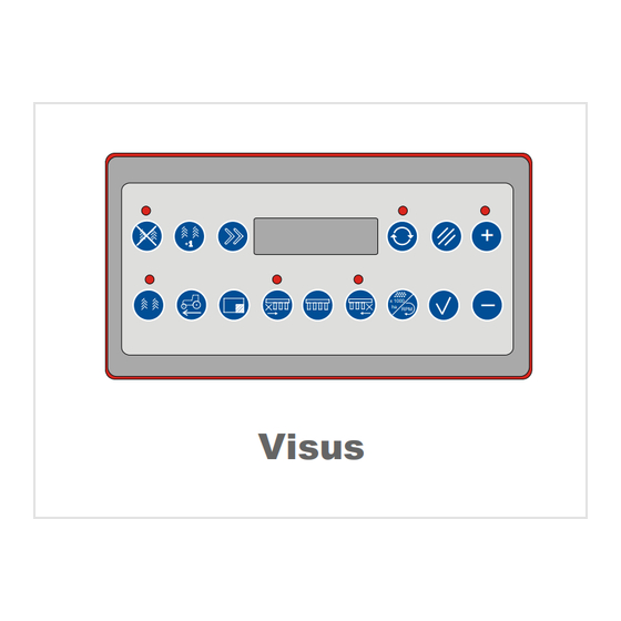
Familiarising yourself with the device An overview of the device Front side The overview shows the display and all keys which have each been allocated a function. The exact functions involved are described in the appropriate place. 1. Cancel entries 2. - Page 10 Familiarising yourself with the device The rear side The overview shows all connections on the back. Base for the bracket for fixing devices Connection for the control cable ON-OFF switch...
-
Page 11: Technical Data
Familiarising yourself with the device Technical data Visus Power supply [V] DC voltage 12 – 14 Fuse [A] • Job computer Protection classes • IP 54 Terminal IP 67 • Job computer Temperature range [°C] -10 to +50 Functions The device has the following functions for pneumatic precision seed- ing machines: •... -
Page 12: Delivery And Assembly
Delivery and assembly Checking the Delivery and assembly For the electrical controller: • scope of delivery Terminal • Bracket for mounting on tractor • Power cable from tractor battery, including socket for mounting on tractor If parts are missing or have been damaged during transportation, please submit a claim immediately to your dealer, importer or the man- ufacturer. -
Page 13: Connecting
Connecting Connecting Prerequisites for connecting up the machine are: • The machine is coupled to the tractor • All components are fitted in an orderly manner • All cables and plugs are in perfect condition Safety Check the cables Check cables before connecting them and replace damaged ca- bles. -
Page 14: Operation
Operation Switching on Operation The system is ready to operate after being connected up and can be switched on. Press the On-Off switch on the terminal The system performs a short self-test. You will then see the current driving speed on the display. ON-OFF switch Using the keys The following is an explanation of the keys required for entering, de-... -
Page 15: Basic Settings
Operation Basic settings A few settings need to be made so that the electronic control system can perform at its best with your machine. Press the key. Press several times to scroll through the options in the selection menu. ... - Page 16 Operation Tramline settings menu Tramlines are laid down for spraying/fertilising units such as field sprayers or fertiliser spreaders. The details of the machine's working width are vital for a correct calculation. → Chapter »Operation«, section »Seeding machine settings menu«, page 18 The tramlines are calculated automatically.
- Page 17 Operation Display of field side where seeding work starts: Beginning the seeding work at the left side of the field Beginning the seeding work at the right side of the field Spraying/fertilising tractor track width If the spraying/fertilising tractor track width has altered, please contact your dealer.
- Page 18 Operation Seeding machine set- Basic settings refer to machine data which is important for controlling tings menu functions or triggering alarms. Enter the working width of the machine in metres Set the value with , save with Selecting the travel sensor Track sensor from seeding machine drive wheel Radar sensor on the tractor If the seeding machine has a drive wheel: Enter number of pulses over...
- Page 19 Machines with more than 12 seed rows are equipped with two job computers. The second job computer must be activated when Visus is first switched on. To do this, connect through all the seed rows once. If the seed rows are not connected through, they cannot all be monitored.
- Page 20 Operation Enter PIN. The subsequent menu items can only be changed using a PIN. Changes should only be made by a trained service technician. Sole responsibility for entries made without the dealer's written author- isation lies with the user. The set values can be displayed for information purposes without us- ing a PIN.
- Page 21 Operation Table for tramline rhythms These values are intended for the trained service technician.
- Page 22 Operation Long black bar: The values for “increased sensitivity” can be adjusted between 5 % and 40 %. Factory setting: 20 % Short black bar: The values for “decreased sensitivity” can be adjusted between 10 % and 60 %. Factory setting: 40 % Test menu The test menu provides a summary of software versions and allows you to check individual seeding machine functions.
- Page 23 Operation Test actuators Activate or deactivate with Test the magnetic coupling on the left side Test the magnetic coupling on the right side Information for the service technician Display of the last active opto-sensor • Left: Number of sowing units •...
- Page 24 Operation The keys The keys and functions are described here in turn, running from left to right, as they occur on the terminal. Switching off the tramlines The tramline sequence is then not counted any further. – x 1000 ha RPM When the key is pressed, its LED comes on to indicate that the tram- line sequence is not being increased.
- Page 25 Operation Display current pass in tramline rhythm For example: 2:4 means that 4 passes are needed for a tramline – x 1000 ha RPM rhythm, and the current pass is no. 2. If a tramline is being set up dur- ing the current pass, the LED above the key comes on for information purposes.
- Page 26 Operation Switch off monitoring of the sowing units starting from the left When the key is pressed, its LED comes on to indicate that at least one sowing unit has been switched off. Activate monitoring for all sowing units: Press the Display of information on which sowing units are being monitored and which sowing units are not.
- Page 27 Operation 1. Confirm entries The values are then saved. The old values are not changed unless this key is pressed. 2. Select menu items 1. Within menus, change values downwards 2. Activate or deactivate functions such as activating or deactivating sensors...
-
Page 28: Tramline Rhythm Instructions
Operation Tramline rhythm The correct tramline rhythm is calculated automatically from the com- bination of the working widths of the seeding machine and the spray- instructions ing/fertilising unit. This chapter is just for information purposes. The tramline rhythm defines when tramlines are to be set up on the field. - Page 29 Operation Setting up tramlines Setting tramlines by blocking the sowing units is dependent on: • The tractor's track width • the width of the spraying/fertilising unit, and • The row spacing Drive over the centre of a seed row Centre Select the number of blocked seed rows so that the tractor tyres do not drive over any seed rows.
- Page 30 Operation The following illustration contains several examples of tramline rhythms. Sowing Fertilising/spraying 1/8 of the working width of the sprayer, or 1/2 of the working width of the seeding machine B/12 1/12 of the working width of the sprayer, or 1/2 of the working width of the seeding machine Numbers, left...
-
Page 31: Removal, Storage
Removal, storage Removal, storage Removal Cable from job computer on seeding machine to terminal Release the screw-on connection Remove plug from rear of terminal Screw-on Plug connection Power cable from job computer to tractor Remove plug from socket on tractor ... -
Page 32: Eliminating Faults
Eliminating faults Eliminating faults Faults can often be eliminated in a fast and easy manner. Before calling Customer Service, refer to the table below to check whether you can eliminate the fault yourself. Fault Cause Remedy • The device cannot be switched The poles of the supply voltage are Have the polarity checked reversed... - Page 33 Eliminating faults Fault Cause Remedy If you get an alarm message, stop and search for the cause of the alarm. Alarms can be confirmed using the key. The audible warning signal will stop and you can look for and elimi- nate the cause of the alarm without being disturbed.
-
Page 34: Disposal
Disposal Disposal When the service life of your device is over, it must be properly dis- posed of. Please observe the currently valid disposal regulations. Plastic parts The plastic parts can disposed of in the normal domestic waste de- pending on specific national regulations (residual waste). Metal parts All machine components can be sent for scrap metal recycling. -
Page 35: Ec Declaration Of Conformity
EC Declaration of Conformity EC Declaration of Conformity In accordance Kverneland Group Soest GmbH Coesterweg 42 with EC Directive D-59494 Soest 2004/108/EG declares under its sole responsibility that the following product com- plies with EC Directive 2004/108/EC: Visus Kverneland Group Soest GmbH Soest, 24.02.2015... -
Page 36: Index
Index Index Alarms Basic settings Conformity Declaration Connecting Connections Display Disposal of the device Eliminating faults Employer Front side Instruction Mode of operation Range of application Removal Safety Scope of delivery Switching on Symbols Technical data...
Need help?
Do you have a question about the Visus and is the answer not in the manual?
Questions and answers