Table of Contents
Advertisement
Quick Links
Advertisement
Table of Contents

Related Manuals for thomann Stairville CLB5 2P RGBWW Compact LED Bar


Summary of Contents for thomann Stairville CLB5 2P RGBWW Compact LED Bar
- Page 1 CLB5 2P RGBWW Compact LED Bar LED Lighting Set...
- Page 2 Thomann GmbH Hans-Thomann-Straße 1 96138 Burgebrach Germany Telephone: +49 (0) 9546 9223-0 Internet: www.thomann.de 05.06.2024, ID: 448711 (V6)
-
Page 3: Table Of Contents
Table of contents Table of contents General information..........................6 1.1 Symbols and signal words....................... 6 Safety instructions............................. 9 Features............................... 13 Installation..............................14 Starting up..............................19 Connections and controls........................21 Operation..............................26 7.1 Starting the device........................... 26 7.2 Remote control..........................26 7.3 Operation on the device........................ - Page 4 Table of contents Plug and connection assignments....................51 Cleaning............................... 52 Protecting the environment......................53 CLB5 2P RGBWW Compact LED Bar LED Lighting Set...
- Page 5 CLB5 2P RGBWW Compact LED Bar LED Lighting Set...
-
Page 6: General Information
Our products and documentation are subject to a process of continuous development. They are therefore subject to change. Please refer to the latest version of the documentation, which is ready for download under www.thomann.de. 1.1 Symbols and signal words In this section you will find an overview of the meaning of symbols and signal words that are used in this document. - Page 7 General information Signal word Meaning DANGER! This combination of symbol and signal word indicates an immediate dangerous situation that will result in death or serious injury if it is not avoided. WARNING! This combination of symbol and signal word indicates a pos‐ sible dangerous situation that can result in death or serious injury if it is not avoided.
- Page 8 General information Warning signs Type of danger Warning – danger zone. CLB5 2P RGBWW Compact LED Bar LED Lighting Set...
-
Page 9: Safety Instructions
Safety instructions Safety instructions Intended use This device is intended for use as an electronic lighting effect by means of LED technology. The device is designed for professional use only and is not suitable for use in households. Use the device only as described in this user manual. - Page 10 Safety instructions DANGER! Danger to life due to electric current! Within the device there are areas where high voltages may be present. Never remove any covers. There are no user-serviceable parts inside. Do not use the device when covers, safety equipment or optical components are missing or damaged. DANGER! Danger to life due to electric current! A short circuit could lead to a fire hazard and risk of death.
- Page 11 Safety instructions NOTICE! Damage to the device if operated in unsuitable ambient conditions! The device can be damaged if it is operated in unsuitable ambient conditions. Only operate the device indoors within the ambient conditions specified in the “Technical specifications” chapter of this user manual. Avoid operating it in environments with direct sun‐ light, heavy dirt and strong vibrations.
- Page 12 Safety instructions NOTICE! Risk of short circuit due to changing the connection wiring during operation! If connection cables of individual spots are removed or replaced during operation, short circuits may occur that can irreparably damage the device. Always disconnect the device from the mains before making any changes to the wiring. NOTICE! Damage to the device by disconnecting LED spots during operation! If individual LED spots are disconnected from the device during operation, the device can get damaged.
-
Page 13: Features
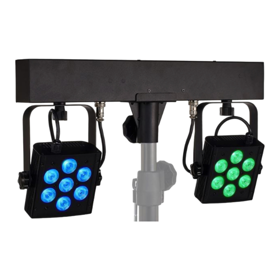
Features Features The LED lighting set provides an ideal combination of warm white and coloured light for the parallel illumination of stages and dance floors in various shades of colour. Two LED spots, each with seven 4-in-1 LEDs, 4 W each, pre-mounted on T-bar Control via DMX (four different modes), via the buttons and display on the device, via foot switch and via infrared remote control Pre-programmed automatic shows... -
Page 14: Installation
Installation Installation Unpack and check carefully there is no transportation damage before using the unit. Keep the equipment packaging. To fully protect the product against vibration, dust and moisture during transportation or storage use the original packaging or your own packaging material suitable for transport or storage, respectively. - Page 15 Installation NOTICE! Damage to the device by disconnecting LED spots during operation! If individual LED spots are disconnected from the device during operation, the device can get damaged. Operate the device only when all LED spots are connected. Always disconnect the device from the mains before removing the LED spots. NOTICE! Risk of overheating and fire due to inadequate distance and bad ventilation! If the distance between the light source and the illuminated surface is too short or...
- Page 16 Installation NOTICE! Potential property damage due to unsuitable stands! If the device is mounted on an unsuitable stand, there is a risk that the stand will fall over and cause damage. Only use stands whose maximum bearing capacity is at least as high as the weight of the device.
- Page 17 Installation Pre-mounted spots The two spots are pre-mounted on the T-bar. Locking screw for fixing the inclination angle Threads for attaching additional effects units or for suspension by means of C-hooks Locking screw for fixing the spots to the T-bar and for their horizontal orientation (dis‐ persion direction) Electrical connection of the spot at the T-bar (pre-mounted) 35 mm flange for attaching the T-bar to a stand...
- Page 18 Installation Inserting the battery into the Push the lock of the battery holder towards the centre of the housing and pull out the battery remote control holder like a drawer. Insert the batteries. The battery is correct if the positive pole points to the housing base of the remote control.
-
Page 19: Starting Up
This equipment uses a frequency range that is free of charge and registration within the European Union. For more information, please visit: http://www.thomann.de. Make sure that no metal objects are located between transmitter and receiver. Avoid interference by other radio and in-ear systems. - Page 20 Starting up Connections in DMX mode Connect the DMX input of the device to the DMX output of a DMX controller or another DMX device. Connect the output of the first DMX device to the input of the second one, and so on to form a daisy chain.
-
Page 21: Connections And Controls
Connections and controls Connections and controls ö & 1 [Power In] | Rubber panel plug for the power supply with fuse holder. 2 [DMX In] | DMX input, designed as XLR panel plug, 3-pin 3 [DMX Out] | DMX output, designed as XLR panel socket, 3-pin 4 [IR] | Infrared receiver for the remote control signals. - Page 22 Connections and controls [Up] | Increases the displayed value by one. [Down] | Decreases the displayed value by one. 6 [Footswitch Input] | 6.35-mm jack socket for connecting the foot switch unit 7 [Power Out] | Rubber panel socket for the power supply of further devices CLB5 2P RGBWW Compact LED Bar LED Lighting Set...
- Page 23 Connections and controls Foot switch unit (item no. 370552, optionally available) ö & Red/Green Indicator Light 1 [Auto Run/Program] | activates the ‘Automatic’ mode (playback of preprogrammed automatic shows). 2 [Sound Active] | activates the ‘Sound-control’ mode (playback of sound-controlled automatic shows). CLB5 2P RGBWW Compact LED Bar LED Lighting Set...
- Page 24 Connections and controls 3 [Freeze] | pauses the running show (’freeze’) and resumes it after a break. 4 [Blackout] | blackouts all LEDs or turns them back on again. 5 [Red/Green Indicator Light] | status LEDs. The red LED lights up when the device is turned on. The green LED flashes when the device is receiving radio signals.
- Page 25 Connections and controls Infrared remote control Since the universal remote control can be used for several device types, some buttons may not (item no. 354223, be assigned and therefore have no function. optionally available) 1 [AUTO] | Activates “Automatic” mode. ö...
-
Page 26: Operation
Operation Operation 7.1 Starting the device Connect the device to the mains to start operation. After a few seconds, the display indicates that a reset is in progress. The device is now operational. 7.2 Remote control The device can only be controlled via the remote control if it is not in “DMX” or “Master/slave” mode. - Page 27 Operation “Pre-programmed automatic Press [PRG]. Use [+] and [–] to select a value between ‘Pr.01’ and ‘Pr.30’ . show” mode Press [STROBE] and then use [+] | [–] to select a value between ‘FS.00’ (slow) and ‘FS.99’ (fast) to switch on a strobe effect. Press [STROBE] again to turn off the strobe effect. Press [SPEED] and then use [+] | [–] to select a value between ‘SP.01’...
- Page 28 Operation Colour selection You can use the coloured buttons to select a colour directly in any mode. The following assign‐ ment applies: Button Colour Button Colour Button Colour Cyan Magenta Crimson Light green Green Pink Light blue Blue Yellow Brown Amber White Warm white...
-
Page 29: Operation On The Device
Operation 7.3 Operation on the device Press [Mode] to activate the main menu and select an operating mode. Use [Setup] to select further options. Use [Up] | [Down] to change the currently displayed value. When the display shows the desired value, press [Mode]. If you do not press any button for about 30 seconds, the display turns off. - Page 30 Operation “Pre-programmed automatic A pre-programmed automatic show can only be activated if the device is operating in stand- show” mode alone mode or as master in a master/slave combination. This setting is only relevant if the device is not controlled via DMX. Press [Mode] repeatedly until the display shows ‘Pro’...
- Page 31 Operation To adjust the speed of the selected automatic show, press [Setup] repeatedly until the display shows ‘SPxxx’ . Now use [Up] | [Down] to select a value between ‘SP.01’ (slow) and ‘SP.99’ (fast) or ‘SP.FL’ . To adjust the flashing frequency, press [Setup] repeatedly until the display shows ‘FL.xx’ . Now use [Up] | [Down] to select a value between ‘FL.00’...
- Page 32 Operation DMX mode This setting is only relevant when the device is controlled via DMX. Press [Mode] repeatedly until the display shows ‘d.xxx’ . Press [Setup]. Now you can set the number of the first DMX channel to be used by the device (DMX address). Use [Up] | [Down] to select a value between 1 and 512 (display shows ‘d.001’...
- Page 33 Operation Sound control A sound-controlled show can only be activated if the device is operating in stand-alone mode or as master in a master/slave combination. This setting is only relevant if the device is not con‐ trolled via DMX. Press [Mode] repeatedly until the display shows ‘Soud’ . Press [Setup] and use [Up] | [Down] to adjust the sensitivity for the built-in microphone between ‘SO.00’...
- Page 34 Operation Dimmer curve Press [Mode] repeatedly until the display shows ‘Set’ . Press [Setup]. Use [Up] | [Down] to select the ‘Cu.SE’ menu item and confirm with [Setup]. Use [Up] | [Down] to select one of the dimmer curves listed below. The dimmer curve deter‐ mines how the brightness increases or decreases depending on the set DMX value.
- Page 35 Operation Dimmer speed Press [Mode] repeatedly until the display shows ‘Set’ . Press [Setup]. Use [Up] | [Down] to select the ‘di.SP’ menu item and confirm with [Setup]. Use [Up] | [Down] to choose the response speed of the dimmer between ‘FASt’ (fast) and ‘SLOW’...
- Page 36 Operation DMX synchronisation Press [Mode] repeatedly until the display shows ‘Set’ . Use [Up] | [Down] to select the ‘Sync’ menu item and confirm with [Setup]. Use [Up] | [Down] to choose how connected devices behave when DMX transmission fails: ‘On’ (devices are synchronised with each other) and ‘Off’...
-
Page 37: Menu Overview
Operation 7.4 Menu overview CLB5 2P RGBWW Compact LED Bar LED Lighting Set... -
Page 38: Functions In 4-Channel Dmx Mode
Operation 7.5 Functions in 4-channel DMX mode Channel Value Function 0…255 Red intensity (0% to 100%) for all LEDs 0…255 Green intensity (0% to 100%) for all LEDs 0…255 Blue intensity (0% to 100%) for all LEDs 0…255 White intensity (0% to 100%) for all LEDs CLB5 2P RGBWW Compact LED Bar LED Lighting Set... -
Page 39: Functions In 8-Channel Dmx Mode
Operation 7.6 Functions in 8-channel DMX mode Channel Value Function 0…255 Red intensity (0% to 100%) for all LEDs of spot 1 0…255 Green intensity (0% to 100%) for all LEDs of spot 1 0…255 Blue intensity (0% to 100%) for all LEDs of spot 1 0…255 White intensity (0% to 100%) for all LEDs of spot 1 0…255... -
Page 40: Functions In 10-Channel Dmx Mode
Operation 7.7 Functions in 10-channel DMX mode Channel Value Function 0…255 Dimmer (0% to 100%) 0…255 Red intensity (0% to 100%) for all LEDs of spot 1 0…255 Green intensity (0% to 100%) for all LEDs of spot 1 0…255 Blue intensity (0% to 100%) for all LEDs of spot 1 0…255 White intensity (0% to 100%) for all LEDs of spot 1... -
Page 41: Functions In 12-Channel Dmx Mode
Operation 7.8 Functions in 12-channel DMX mode Channel Value Function 0…255 Dimmer (0% to 100%) 0…255 Red intensity (0% to 100%) for all LEDs of spot 1 0…255 Green intensity (0% to 100%) for all LEDs of spot 1 0…255 Blue intensity (0% to 100%) for all LEDs of spot 1 0…255 White intensity (0% to 100%) for all LEDs of spot 1... - Page 42 Operation Channel Value Function 32…39 Pre-programmed automatic show 04 40…47 Pre-programmed automatic show 05 48…55 Pre-programmed automatic show 06 56…63 Pre-programmed automatic show 07 64…71 Pre-programmed automatic show 08 72…79 Pre-programmed automatic show 09 80…87 Pre-programmed automatic show 10 88…95 Pre-programmed automatic show 11 96…103 Pre-programmed automatic show 12...
- Page 43 Operation Channel Value Function 160…167 Pre-programmed automatic show 20 168…175 Pre-programmed automatic show 21 176…183 Pre-programmed automatic show 22 184…191 Pre-programmed automatic show 23 192…199 Pre-programmed automatic show 24 200…207 Pre-programmed automatic show 25 208…215 Pre-programmed automatic show 26 216…223 Pre-programmed automatic show 27 224…231 Pre-programmed automatic show 28...
- Page 44 Operation Channel Value Function 48…63 R: 0; G: 0; B: 255; W: 0; 64…79 R: 0; G: 0; B: 0; W: 255 80…95 R: 255; G: 150; B: 0; W: 0; 96…111 R: 255; G: 180; B: 0; W: 0; 112…127 R: 255;...
- Page 45 Operation Channel Value Function 0…8 Sound-controlled mode 01 9…17 Sound-controlled mode 02 18…26 Sound-controlled mode 03 27…35 Sound-controlled mode 04 36…44 Sound-controlled mode 05 45…53 Sound-controlled mode 06 54…62 Sound-controlled mode 07 63…71 Sound-controlled mode 08 72…80 Sound-controlled mode 09 81…89 Sound-controlled mode 10 90…98...
- Page 46 Operation Channel Value Function 144…152 Sound-controlled mode 17 153…161 Sound-controlled mode 18 162…170 Sound-controlled mode 19 171…179 Sound-controlled mode 20 180…188 Sound-controlled mode 21 189…197 Sound-controlled mode 22 198…206 Sound-controlled mode 23 207…215 Sound-controlled mode 24 216…224 Sound-controlled mode 25 225…233 Sound-controlled mode 26 234…242...
-
Page 47: Resetting To Factory Defaults
Operation Channel Value Function 0…4 No strobe effect 5…255 Strobe effect, increasing speed 7.9 Resetting to factory defaults Proceed as follows to reset the device to factory defaults: Press [Mode] repeatedly until the display shows ‘Set’ . Use [Up] | [Down] to select the ‘-rSt’ menu item and confirm with [Setup]. -
Page 48: Technical Specifications
Technical specifications Technical specifications Light source 14 × RGBWW LEDs, each 4 W 253 mm Optical properties Beam angle approx. 40° Dimmer Electronic, 0…100% Shutter Electronic, 0…20 Hz Control IR remote control (available as an option) Foot switch unit (available as an option) Number of DMX channels 4, 8, 10, 12 Input connections... - Page 49 Technical specifications Supply voltage 100 - 240 V 50/60 Hz Fuse 5 mm × 20 mm, 2 A, 250 V, slow blow Transmitting frequency of radio antenna 2.4 GHz Max. transmission power 100 mW Battery remote control Battery type Lithium button cell, 3 V, CR 2025 International Protection Rating IP20 Mounting options...
- Page 50 Technical specifications Further information Spotlight included Effect devices included Controller included Stand included Case/bag included CLB5 2P RGBWW Compact LED Bar LED Lighting Set...
- Page 51 Plug and connection assignments Plug and connection assignments Introduction This chapter will help you select the right cables and plugs to connect your valuable equip‐ ment so that a perfect light experience is guaranteed. Please take our tips, because especially in ‘Sound & Light’ caution is indicated: Even if a plug fits into a socket, the result of an incorrect connection may be a destroyed DMX controller, a short circuit or ‘just’...
- Page 52 Cleaning Cleaning Optical lenses Clean the optical lenses, that are accessible from the outside, regularly in order to optimize the light output. The frequency of cleaning depends on the operating environment: wet, smoky or particularly dirty surroundings can cause more accumulation of dirt on the optics of the device.
- Page 53 Protecting the environment Protecting the environment Disposal of the packing material Environmentally friendly materials have been chosen for the packaging. These materials can be sent for normal recycling. Ensure that plastic bags, packaging, etc. are disposed of in the proper manner. Do not dispose of these materials with your normal household waste, but make sure that they are collected for recycling.
- Page 54 When disposing of the device, comply with the rules and regulations that apply in your country. You can also return your old device to Thomann GmbH at no charge. Check the current conditions on www.thomann.de.
- Page 56 Musikhaus Thomann · Hans-Thomann-Straße 1 · 96138 Burgebrach · Germany · www.thomann.de...
Need help?
Do you have a question about the Stairville CLB5 2P RGBWW Compact LED Bar and is the answer not in the manual?
Questions and answers