Table of Contents
Advertisement
Quick Links
Advertisement
Table of Contents

Subscribe to Our Youtube Channel
Related Manuals for Visionix briot couture


Summary of Contents for Visionix briot couture
- Page 1 User Manual-Blocker FC001204-rev02...
- Page 2 BRIOT COUTURE… User manual Installation 1.1. Unpacking the machine 1.1.1. Warning 1.1.2. Unpacking 1.2. Setting up 1.2.1. Workbench preparation 1.2.2. Installation 1.2.3. Machine connection 1.3. Turning on the machine 1.3.1. Switching the machine on 1.3.2. Switching the machine off 1.4.
- Page 3 BRIOT COUTURE… User manual 3.6. Operation Turning on the Briot Couture 3.7. Working Operation Data Management Recording the shape with Gravitech™ “Edged or demo lens” Measuring the Frame “Shape creator” function Drilling plan Positioning of an eyeglass lens Centring a lens Shape change –...
- Page 4 BRIOT COUTURE… User manual Replace the Touch Latch Changing a fuse 6.4. Touch screen MAINTENANCE Cleaning the touch screen 6.5. Preventive maintenance Recommendations Replacement table for standard parts 6.6. Messages Types of messages Message list Technical specifications 7.1. Technical specifications Appendix 8.1.
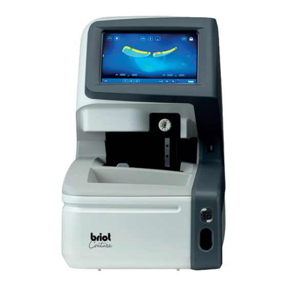
- Page 5 Dear Customer, You have purchased an BRIOT COUTURE machine, and the entire team of Briot, a brand belonging to the Luneau Technology group, would like to thank you for the confidence you have shown us. The BRIOT COUTURE machine is a laboratory machine designed for opticians and is used for carrying out operations such as creating fittings and centering and blocking spectacle lenses.
- Page 6 BRIOT COUTURE … User manual Θ GRAPHIC CODE Different graphic codes have been used in this manual to allow the user to distinguish between different types of information and easily spot the items which demand special attention (e.g. safety-related items).
-
Page 7: Installation
INSTALLATION... -
Page 8: Unpacking The Machine
BRIOT COUTURE … User manual 1.1. UNPACKING THE MACHINE 1.1.1. W ARNING Ensure that the machine is placed in accordance with the TOP and BOTTOM signs on the box. Place the machine on a flat and stable surface. - Page 9 Provide a mark measuring of 360 mm x 600 mm on the workbench Do not place any obstacles (cabinet, shelf, etc.) lower than 600 mm above the workbench. Allow sufficient distance between the BRIOT COUTURE blocker and the edger. Note: the standard connection lead is 5m long.
-
Page 10: Machine Connection
BRIOT COUTURE … User manual 1.2.3. M ACHINE CONNECTION Make sure you have: Connect the supplied electric lead to the power socket. An electrical socket: 2-phase + Ground A power line protected by a 30 mA differential circuit breaker Sector If you connect the machine to the HOST network: connect the cable to the HOST port using the RS232 cable provided. -
Page 11: Turning On The Machine
BRIOT COUTURE … User manual 1.3. TURNING ON THE MACHINE 1.3.1. S WITCHING THE MACHINE ON To turn on the machine, follow the steps below: Press the Start/Stop switch, Press the pushbutton, located at the rear of the located at the bottom front machine. -
Page 12: Machine Presentation
BRIOT COUTURE … User manual 1.4. MACHINE PRESENTATION Touch screen Blocker USB port Centering area and optical tracer Mechanical tracer Pushbutton USB port RJ45 port HOST port Switch EDGER port Power supply cable COUTURE... -
Page 13: Precautions For Use
PRECAUTIONS FOR USE... -
Page 14: Lithium Battery
BRIOT COUTURE … User manual 2.1. SAFETY 2.1.1. O PERATOR Read the instructions carefully and always keep the CD-Rom containing the user manual near the machine in order to be able to refer to it easily. Before carry out any work on the machine, check that the mains cable is unplugged. - Page 15 BRIOT COUTURE … User manual 2.2. RECOMMENDATIONS 2.2.1. G ENERAL Clean the machine regularly. Comply with the machine maintenance messages. Protect the machine's power cords. Use blocks designed and supplied by Briot. Use new adhesives.
- Page 17 BRIOT COUTURE … User manual 3.1. SPECIFIED LENS TYPES IMITS Eyeglass lenses Single vision lens Bifocal lens Trifocal lens Executive lens Progressive lens Prism lens Figure 1 Lens illustration example Dimensions Diameter Ø Ø 45 mm to Ø 80 mm (min./max.) Height (centre of h = 19 mm (max.)
- Page 18 Lens with high, curved, or flat segment (flat top) Trifocal lens and executive lens Alignment should only be done manually or by 3-dot centring. If the Briot Couture cannot automatically determine the lens parameters, the manual blocking mode is started. Progressive lens Lens with an axis characterised by at least two separate segments and one of the optical centres shown below.
- Page 19 BRIOT COUTURE … User manual 3.2. USING THE BRIOT COUTURE SING THE CREEN The following symbols explain the gestures used in this operator’s manual in connection with the multitouch display/control panel: Gesture Description • Tap briefly using one finger (button).
- Page 20 BRIOT COUTURE … User manual ISPLAY AND INDICATION The following table describes the different display variations for symbols and numerical values and their meanings: Gesture Description Inactive selection button Activated selection button Confirmation button not pressed Confirmation button pressed Cancel/quit action...
- Page 21 BRIOT COUTURE … User manual NPUT INES AND EYBOARDS EYPADS Figure 2 Input lines All input lines work according to the same principle. Press button (B-1) on the “Trace” screen (B-9) once to call up the job window. ...
- Page 22 BRIOT COUTURE … User manual 3.3. OVERVIEW OF FUNCTIONAL PARTS Figure 4 Functional parts Designation Designation Multi-Touch-Display Lens clamping chuck Blocker Gravitech optical tracer Mechanical tracer This overview only covers the functional parts relevant in working operation. A detailed description of all device components can be found in Section 1, “Instal- lation.”...
- Page 23 BRIOT COUTURE … User manual 3.4. MULTI-TOUCH-DISPLAY (B) ASIC UTTONS Figure 5 Multitouch display basic buttons Operating element Function Button Record new job Button Show job list Button Notification of incoming external 3D data Button Call up menu for recording/modifying drilling data...
- Page 24 BRIOT COUTURE … User manual 3.4.1.1. (B-1) UBMENU B-1.1 B-1.2 B-1.3 Figure 6 “New Job” multitouch display Operating element Function B-1.1 Input field Record/input new job number B-1.2 Job List List already existing jobs B-1.3 Keyboard/keypad Input job number via keys ...
- Page 25 BRIOT COUTURE … User manual 3.4.1.2. (B-2) UBMENU B-2.1 B-2.2 B-2.3 A-2.1 B-2.4 B-2.5 A-2.2 A-2.3 Figure 7 “Job List” multitouch display Operating element Function Sort job list by job number in ascending or descending B-2.1 Sort by job number...
-
Page 26: Using The Main Functions
BRIOT COUTURE … User manual 3.5. USING THE MAIN FUNCTIONS “T ” (B-9) RACE BUTTONS BEFORE TRACING B-9.1 B-9.2 B-9.3 B-9.6 B-9.4 B-9.7 B-9.5 Figure 8 “Trace” multitouch display Operating element Function Activate Gravitech optical tracer B-9.1 Button → Section 3.5.4: “Record shape”... - Page 27 BRIOT COUTURE … User manual 3.5.1.1. (B-9.3) UBMENU HAPE RCHIVE B-9.3a B-9.3b B-9.3c B-9.3d B-9.3e B-9.3f A-9.31 A-9.32 A-9.33 B-9.3g A-9.34 Figure 9 “Shape Archive” multitouch display Operating element Function Sort shape list by manufacturer in ascending or de- B-9.3a...
- Page 28 BRIOT COUTURE … User manual “T ” (B-9) RACE BUTTONS AFTER TRACING 3.5.2.1. (B-9.2) ECHANICAL TRACING PROCESS A-9.2al B-9.2j B-9.2l B-9.2k Figure 10 “Mechanical tracing process” multitouch display Operating element Function B-9.2j Button Measure metal frame B-9.2k Button Measure plastic frame B-9.2l...
- Page 29 BRIOT COUTURE … User manual “T ” RACE BUTTONS PARAMETERI (B-9.2) B-9.2a B-9.2b B-9.2c B-9.2d B-9.2e B-9.2f B-9.2g B-9.2h B-9.2i B-9.2p B-9.2o B-9.2n B-9.2m Figure 11 “Mechanical Tracing menu parameterised” multitouch display The list with the descriptions of the buttons is given on the following page.
- Page 30 BRIOT COUTURE … User manual Operating element Function B-9.2a Button Input/display bridge width (AZG) B-9.2b Button Save recorded data as template B-9.2c Button Align shape axis B-9.2d Button Adjust frame base curve B-9.2e Button Set wrap angle (FSW) (Z-tilt) Open: Transfer shape circumference when mirroring B-9.2f...
- Page 31 A-9.2d11 FSW scale Scale providing visual orientation for adjustment You can stop the frame on the Briot Couture multitouch display in order to de- termine the wrap angle. → Description of confirmation fields in Section 3.1.1.2, “Display and indication”...
- Page 32 BRIOT COUTURE … User manual “R ” ECORD SHAPE BUTTONS ™ (B-9.1) PARAMETERISED WITH GRAVITECH B-9.1b B-9.1a B-9.1c B-9.c B-9.1d B-9.1e B-9.1f B-9.1g A-9.1c A-9.1b A-9.1a B-9.1h B-9.1i Figure 13 “Record shape menu parameterised” multitouch display Operating element Function B-9.1a...
- Page 33 BRIOT COUTURE … User manual Allowance: +0.2 mm, proportional B-9.1g Button (Value is adjustable; see standard parameters.) B-9.1h Button Enter allowance manually B-9.1i Button No compensation / no allowance A-9.1a Display Number of detected slots A-9.1b Display Number of detected open-ended holes (edge holes) A-9.1c...
- Page 34 BRIOT COUTURE … User manual “CENTRE/B ” B (B-8) LOCK UTTONS B-8.1 B-8.2 B-8.3 B-8.4 B-8.5 B-8.6 B-8.7 B-8.8 B-8.9 B-1h.6 Figure 14 “Centre/Block” multitouch display Operating element Function B-8.1 Button Transfer right centring and lens parameters to left lens B-8.2...
- Page 35 BRIOT COUTURE … User manual 3.5.5.1. UBMENU EASURE EYEGLASS LENS BASE CURVE (B-8.9) A-8.91 A-8.92 B-8.9a B-8.9b Figure 15 “Measure base curve” multitouch display Operating element Function Record base curve of lens with Gravitech optical A-8.91 Measurement window tracer (4) A-8.92...
- Page 36 BRIOT COUTURE … User manual “3D S ” (B-7) IMULATION BUTTONS B-7.6 B-7.9 B-7.1 B-7.2 B-7.3 B-7.4 B-7.5 B-7.7 B-7.8 B-7.10 B-7.11 B-7.12 B-7.13 Figure 16 “3D Simulation” multitouch display Operating element Function B-7.1 Button Lens with bevel active B-7.2...
-
Page 37: Operation
Briot Couture has been properly commissioned and is set up stably. Power connector is inserted on back of Briot Couture. Power switch on back of Briot Couture is set to “I” position. Press pushbutton (T-1) to turn on the Briot Couture. ... -
Page 38: Working Operation
BRIOT COUTURE … User manual 3.7. WORKING OPERATION ANAGEMENT 3.7.1.1. REATING A B-AZ The empty field (B-AZ) shows that no job is currently selected. Press button (B-1) on the “Trace” screen (B-9) once to call up the job window. -
Page 39: Opening An Existing Job
BRIOT COUTURE … User manual 3.7.1.2. PENING AN XISTING At least one job has already been created. A job can also be opened if an- other job is already active. The previously active job is closed and saved. - Page 40 BRIOT COUTURE … User manual 3.7.1.3. REATING A SHAPE TEMPLATE A new job has been created and is active. A demo lens or a frame has been measured. Call up the screen for adding new shape templates by pressing but- ton (B-9.2b) on the “Trace”...
- Page 41 BRIOT COUTURE … User manual 3.7.1.4. PPLYING A SHAPE TEMPLATE At least one shape template has already been saved. A new job has been created and is active. Saved shape templates allow you to work with glasses data without prior measurement.
- Page 42 BRIOT COUTURE … User manual ™ ECORDING THE SHAPE WITH RAVITECH “E ” DGED OR DEMO LENS A new job has been created and is active. Place the frame on a flat surface and mark the desired lens with the supplied felt pen marking tool (TL-1).
- Page 43 BRIOT COUTURE … User manual B-9.1 Press button (B-9.1) by tapping on it once to start the process of recording the shape. The screen switches to trace mode. The GravitechTM optical tracer (4) is active. Press button (B-9.7) to start the process without including the drill holes.
- Page 44 BRIOT COUTURE … User manual EASURING THE RAME A new job has been created and is active. Pull the handle (2.1) on the me- chanical tracer (2) outward and hold in position. The mechanical tracer (2) is open and ready for use.
- Page 45 BRIOT COUTURE … User manual Press -9.2) by tapping on it once to record the frame. The screen switches to trace mode. B-9.2 The mechanical tracer traces the frame (L/R). Press button (B-9.4) to measure B-9.4 the left side individually.
- Page 46 BRIOT COUTURE … User manual Place one finger on the multi- touch display (B) and rotate it on the screen surface to orbit around the 3D model of the frame. The screen for adjustment of the bevel in the cross section enables fine adjustment of the bevel po- sition and its progression.
- Page 47 BRIOT COUTURE … User manual “S ” HAPE CREATOR FUNCTION A new job has been created and is active. Offset tool is on hand. The “Shape creator” function can be used for tracing lenses in in- stalled condition.
- Page 48 BRIOT COUTURE … User manual Place the auxiliary axis (H-1) over the reference holes and lock it by tapping the snap tool button (B-9.6c). B-9.6b The frame is aligned with the auxiliary axis. The shape can now be recon- structed.
- Page 49 BRIOT COUTURE … User manual The number of generated points is displayed in the information box next to button (B-9.6b). Press and hold button (B-9.6d) to delete incorrectly placed or un- necessary points. B-9.6b Press the confirmation button to conclude the process.
-
Page 50: Drilling Plan
BRIOT COUTURE … User manual RILLING PLAN 3.7.5.1. ESCRIPTION OF BUTTONS B-4.1 B-4.2 B-4.3 B-4.4 B-4.5 B-4.6 B-4.7 B-4.8 B-4.11 B-4.10 B-4.9 Figure 29 “Drilling Plan” multitouch display Operating element Function Activate creation of a drill hole. The number of drill B-4.1... - Page 51 BRIOT COUTURE … User manual B-4.17 B-4.16 B-4.15 B-4.14 B-4.13 B-4.12 Figure 30 “Drilling Plan” multitouch display Operating element Function B-4.12 Button Drill stepped through hole. B-4.13 Button Drill blind hole. B-4.14 Button Drill through hole. Delete selected drill holes.
- Page 52 BRIOT COUTURE … User manual 3.7.5.2. REATING A DRILLING PLAN A new job has been created and is active. Lens has been measured or shape template is loaded. The “Create drilling plan” func- tion can be used for planning and simultaneously defining drill holes and their positioning.
- Page 53 BRIOT COUTURE … User manual OSITIONING OF AN EYEGLASS LENS A new job has been created and is active. Eyeglass lens is on hand. Ensure that the clamping chuck is open. Tap button (B-9.6) once. The screen for aligning the frame in a live image opens.
- Page 54 BRIOT COUTURE … User manual ENTRING A LENS 3.7.7.1. ECENTRATION DATA A new job has been created and is active. Frame has been measured or shape template is loaded. Tap button (B-8) once. The display switches to the “Cen- tre”...
- Page 55 BRIOT COUTURE … User manual 3.7.7.2. ENTRING A ROGRESSIVE → Section 3.7.6.1: Decentration data → Section 3.7.5: “Positioning a Lens” Automatic centring only works with single vision and prism lenses. Check the measured data against the inscription. Tap button (1) once to view the centring in detail.
- Page 56 BRIOT COUTURE … User manual Double-click the zoomed region to zoom back out. Confirm the adjusted engraving via the “ ” button. The superimposed shape is dis- played with the lens. If the wavefront measurement was activated at the start and you want to display it, tap button (2) once.
- Page 57 BRIOT COUTURE … User manual Tap the “ “ button once to con- firm. In this case, the power in the near zone is displayed. Tap button (3) to block the lens. The lens is blocked. → Section 3.5.5: “Centre/Block”...
- Page 58 BRIOT COUTURE … User manual 3.7.7.3. ENTRING A BIFOCAL LENS A suitable lens is in position. → Section 3.7.6.1: Decentration data → Section 3.7.5: “Positioning a Lens” Check the measured data and the centring using the near seg- ment.
- Page 59 BRIOT COUTURE … User manual 3.7.7.4. ENTRING A PRISM LENS Tap button (B-8.6) once. The input fields for adding the base of the prism width (B-8.6a) and the prism angle (B-8.6b) ap- pear. Tap once on an individual value to change it.
- Page 60 BRIOT COUTURE … User manual 3.7.7.5. ENTRING A TRIFOCAL LENS Trifocal lens is inserted. Tap button (B-8.7) once. → Section 3.2.3: Input Lines and B-8y B-8z Keyboards/Keypads Tap the respective red cross hairs (B-8z) to start automatic centring.
- Page 61 BRIOT COUTURE … User manual 3.7.7.6. UTOMATIC CENTRING OF A SINGLE VISION LENS A new job has been created and is active. Frame has been measured or shape template is loaded. Decentration data have been recorded. ...
- Page 62 BRIOT COUTURE … User manual 3.7.7.7. ANUAL CENTRING OF THE LENS A new job has been created and is active. Frame has been measured or shape template is loaded. Decentration data have been recorded. A suitable lens is in position.
- Page 63 BRIOT COUTURE … User manual Tap button (K) once to select. The contour adjustment screen opens. The contour can be shifted with the arrow keys. Contour areas that are outside the lens are shown in red. The yellow contour reference (KF) must be positioned to be in- side the lens area.
- Page 64 BRIOT COUTURE … User manual – HAPE CHANGE DIGIFORM FUNCTION 3.7.8.1. IMPLE SHAPE CHANGE A new job has been created and is active. Tap button (B-5) once. The display switches to the “Shape change” screen. → Section 3.2.2: Display and indi- cation →...
- Page 65 BRIOT COUTURE … User manual → Section 3.2.3: Input Lines and Keyboards/Keypads In closed mode, the addition re- gion can only be changed propor- tionally. The addition region can be indi- vidually changed in open mode. Figure 43 Simple shape change 3-50 CT.7...
- Page 66 BRIOT COUTURE … User manual 3.7.8.2. ARIABLE SHAPE CHANGE → Section 3.2.3: Input Lines and Keyboards/Keypads Tap button (VF) once. The screen for variable adjust- ment of the shape change opens. To shift the boundary lines, hold and drag (1) and (2).
- Page 67 BRIOT COUTURE … User manual → Section 3.2.3: Input Lines and Keyboards/Keypads Reposition the drill holes again and then confirm. Figure 45 Variable shape change 3-52 CT.7...
- Page 68 BRIOT COUTURE … User manual 3.7.8.3. HAPE CORRECTION Tap button (VK) once. The shape correction screen opens. → Section 3.2.3: Input Lines and Keyboards/Keypads To shift the boundary lines, hold and drag (1) and (2). Press button (4) to enlarge the view.
- Page 69 BRIOT COUTURE … User manual Press button (4) to enlarge the view. View of section of shape in en- larged mode View of corrected section of shape in enlarged mode Tap button (5) to correct the se- lected region tangentially.
- Page 70 BRIOT COUTURE … User manual View of tangentially corrected section of shape in enlarged mode Press button (6) to confirm the adjustments. → Section 3.2.3: Input Lines and Keyboards/Keypads Press the “ ” button and con- firm the changes made to the shape.
- Page 71 BRIOT COUTURE … User manual 3.8. SIMULATION (VIRTUAL 3D) ECORDING THE PATIENT DATA A new job has been created and is active. Lens/frame has been measured or shape template is loaded. Decentration data have been recorded. ...
- Page 72 BRIOT COUTURE … User manual ECORDING THE REFRACTION DATA B-7.11 Tap button (B-7.11) once. The display switches to the “Rx Data” screen. The sphere (B.7.11.s) and cylin- B-7.11s B-7.11z B-7.11z B-7.11.s der (B-7.11z) parameters are given in the Rx data.
- Page 73 BRIOT COUTURE … User manual ECORDING THE LENS DATA B-7.14 Tap button (B-7.12) once. The parameters are identical for both glasses sides. Tap button (B-7.14) once. The lens geometry simulation opens. B-7.12b B-7.12a B-7.12 B-7.12c B-7.14a Tap button (B-7.14a) once.
- Page 74 BRIOT COUTURE … User manual 3D A DJUSTMENT B-7.13e Tap button (B-7.13) once. The model can now rotate three- dimensionally about its own cen- tre. Press button (B-7.13a) to show the lens bevel and parameters: B-7.13a: Bevel width ...
- Page 75 BRIOT COUTURE … User manual Tap the desired glasses side with your finger. The screen for viewing and ad- justing the frame and bevel in the cross section opens. B-7.POS B-7.15a By sliding the slide control later- ally (B-7.POS), you can shift the viewing position of the bevel.
- Page 76 BRIOT COUTURE … User manual ROSS ECTION FOR RIMLESS NYLOR FRAMES Groove of a full-rim frame or edge of a demo lens has been traced. The screen for adjustment of the groove in the cross section ena- bles fine adjustment of the bevel position and its progression.
- Page 77 BRIOT COUTURE … User manual B-7.a4 Press button (B-7.a4). The percentage mode is started. Button (B-7.a) specifies a contin- uous percentage distance of the groove from the edge. B-7.13a B-7.13c B-7.a5 Press button (B-7.a6). Automatic mode is started.
-
Page 78: Blocking A Lens
BRIOT COUTURE … User manual 3.9. BLOCKING A LENS A new job has been created and is active. Lens/frame has been measured or shape template is loaded. Decentration data have been recorded. Lenses are centred. ... - Page 79 BRIOT COUTURE … User manual Remove an adhesive pad from the blister and stick it on the block (1.1). Grasp the backing paper on the positioned adhesive pad by the tab and pull off. Part of the backing paper re- mains on the adhesive pad to fa- cilitate handling.
- Page 80 BRIOT COUTURE … User manual The corresponding lens must be clamped in the lens clamping chuck (3). The numerical values in fields (1.1v) and (1.1h) determine the distance between the green axis and the violet axis. The two axes must be lined up with the markings and engrav- ings on the lens to be blocked.
- Page 81 CONFIGURATION...
- Page 82 BRIOT COUTURE … User manual 4.1. DESCRIPTION ONFIGURATION SCREEN ACCESS The main entering or centering screen provides access to the technical user menus used to adjust your machine. COUTURE...
- Page 83 BRIOT COUTURE … User manual To access the available menus (as in the example in orange below), scroll the screens to the desired menu (1). You can also access a screen containing the machine's settings by pinching the screen (2).
-
Page 84: Settings Screens
BRIOT COUTURE … User manual 4.2. SETTINGS SCREENS USTOMIZATION MENU You have now selected the Customization screen 4.2.1.1. ONFIGURE DATE AND TIME To configure the date and time of your machine, proceed as follows: Change the time zone before changing the time. - Page 85 BRIOT COUTURE … User manual 4.2.1.2. ETTING THE OPERATOR LANGUAGE To set the default operator language, follow the steps below: 4.2.1.3. ONFIGURE THE KEYBOARD COUTURE...
-
Page 86: Settings Details
BRIOT COUTURE … User manual 4.2.1.4. ETTING THE DEFAULT SETTINGS To set the default parameters, follow the steps below: 4.2.1.4.1. ETTINGS DETAILS Activate or deactivate the Delta X powers display Half-pupillary + or - cylinder distance configuration Configuration of prisms Delta Y (Tabo, etc.) -
Page 87: Information Menu
BRIOT COUTURE … User manual Optical tracer oversize Automatic detection of side in optical plotter Activation/Deactivation of offset blocking* Activate or deactivate the mechanical plotter Auto-Correct Default oversize GraviTech® Shape Contours Value of the oversize + Value of the oversize ++ NOTE: The oversize values are accumulated. -
Page 88: Machine Adjustment
MACHINE ADJUSTMENT... - Page 89 BRIOT COUTURE … User manual 5.1. DESCRIPTION CCESS TO THE ADJUSTMENT SCREENS The main entering or centering screen provides access to the technical user menus used to adjust your machine. COUTURE...
- Page 90 BRIOT COUTURE … User manual To access the available menus (as in the example in orange below), scroll the screens to the desired menu (1). You can also access a screen containing the machine's settings by pinching the screen (2).
- Page 91 BRIOT COUTURE … User manual Mechanical tracer Blocker adjustment adjustment ECHANICAL TRACER ADJUSTMENT COUTURE...
- Page 92 BRIOT COUTURE … User manual You have now selected the Adjustment screen: Carry out the mechanical plotter adjustment: Step 1: Position the tool in the mechanical plotter and then confirm to start the adjustment COUTURE...
- Page 93 BRIOT COUTURE … User manual CAUTION! Make sure that the white dowels are properly positioned at the holes of the tool and the circle on the right The default value corresponds to the tool that was supplied with your machine.
- Page 94 BRIOT COUTURE … User manual Step 2: Save the settings LOCKER ADJUSTMENT Place the tool in the blocker head. CAUTION: To position the tool properly on the blocker, insert the keyway between the two red dots marked on the blocker.
- Page 95 BRIOT COUTURE … User manual On completion of adjustment, you can to remove the adjustment tool. COUTURE...
-
Page 96: Maintenance
MAINTENANCE... - Page 97 BRIOT COUTURE … User manual 6.1. DESCRIPTION To guarantee your machine's performance, you must perform several maintenance operations regularly and make sure you configure and adjust your machine according to the use you want to make of it. The main user technical screen provides access to the user technical menus, including Maintenance, as shown in orange...
- Page 98 BRIOT COUTURE … User manual ANUAL PURGING OF FITTINGS DATABASES To purge your fittings databases more than 30 days* old, follow the steps below: Non-blocked fittings Blocked fittings Edged fittings Note: Purging is only carried out when the button is pressed.
- Page 99 BRIOT COUTURE … User manual 6.2. MECHANICAL PLOTTER MAINTENANCE LEANING THE MECHANICAL PLOTTER To clean the mechanical plotter, follow the steps below: Switch OFF the machine if it is ON. Lift the stylus head manually. Using a brush, clean the stylus head making sure the dust does not fall into the mechanical tracer.
- Page 100 BRIOT COUTURE … User manual 6.3. CENTERING DEVICE/BLOCKER MAINTENANCE LEAN THE BEARING SURFACE To clean the bearing surface, follow the steps below: Remove any component that may hinder proper performance of the operation. Clean with a soft, dry, grease-free and lint-free cloth.
-
Page 101: Changing A Fuse
BRIOT COUTURE … User manual HANGING A FUSE To change a fuse, follow the steps below: Switch the machine off using the pushbutton located at the front of the machine, and then using the switch located at the rear of the machine. -
Page 102: Preventive Maintenance
By making sure to only use parts recommended by the manufacturer you will optimise your machine's working life. EPLACEMENT TABLE FOR STANDARD PARTS 6.5.2.1. CCESSORIES The accessories delivered with the BRIOT COUTURE Blocker are as follows: Accessory L.T.O part number Case provided with foam... -
Page 103: Types Of Messages
BRIOT COUTURE … User manual 6.6. MESSAGES YPES OF MESSAGES There are three types of messages: Information messages, Warning messages, Error messages. ESSAGE LIST The following tables list the most common messages that may appear whilst using the machine together with the possible solutions. -
Page 104: List Of Error Messages
BRIOT COUTURE … User manual Problem No. Message title Display condition(s) 1104 Frame moved. 2008 Please remove any glass present in the blocker. Open the jaws and remove any glass present in the 2010 blocker. 2016 Save settings? Cylinder axis not detected. - Page 105 BRIOT COUTURE … User manual Problem No. Message title Display condition(s) 1991 Motor turret translation failure. Software error: motor control outside its operating range 1991 Motor turret translation failure. Switch cannot be pushed in 1991 Motor turret translation failure. Switch cannot be released 1991 Motor turret translation failure.
- Page 106 BRIOT COUTURE … User manual Problem No. Message title Display condition(s) 2100 Motor blocker X failure. Step loss detected during movement 2101 Motor blocker Y failure. Software error in the movement sequencers 2101 Motor blocker Y failure. Software error: motor control outside its operating range 2101 Motor blocker Y failure.
-
Page 107: Technical Specifications
TECHNICAL SPECIFICATIONS... - Page 108 BRIOT COUTURE … User manual 7.1. TECHNICAL SPECIFICATIONS The general characteristics of the BRIOT COUTURE blocker are as follows: • Dimensions: ✓ Width: 360 mm ✓ Depth: 565 mm ✓ Height: 590 mm • Weight: 29.5 kg • Fitting memory capacity: 5,000 fittings •...
- Page 109 APPENDIX...
-
Page 110: Description Of Buttons
BRIOT COUTURE … User manual 8.1. DESCRIPTION OF BUTTONS 8.1.1. B UTTONS COMMON TO THE SCREENS : Calling up a fitting : Accessing the list of existing fittings : Accessing the list of patterns in memory : Saving a pattern... - Page 111 BRIOT COUTURE … User manual : Reverse the job sides (L/R) : Conduct a symmetric copy : Perform a back-up on an external server (option) : Value of frame groove base : Tilt of frame (Z-tilt) 8.1.3. C ENTERING SCREEN BUTTONS...
- Page 112 BRIOT COUTURE … User manual 8.1.4. O FFSET SCREEN BUTTONS : Axis moved downwards : Axis moved to the right : Axis moved to the left : Axis moved upwards : Axis rotated to the right : Axis rotated to the left...
- Page 113 BRIOT COUTURE … User manual 8.1.6. D RILLING SCREEN BUTTONS : Selected hole moved downwards : Selected hole moved to the right : Selected hole moved to the left : Selected hole moved upwards : Selecting the drilled hole parallel to the clamping shafts...
- Page 114 BRIOT COUTURE … User manual 8.1.7. L IST OF FITTINGS SCREEN BUTTONS : Sort by barcode number : Sort by date : Enter information about the selected fitting 8.1.8. L IST OF PATTERNS SCREEN BUTTONS : Sort by barcode number...
- Page 115 LUNEAU TECHNOLOGY SAS 2 Rue Roger Bonnet, 27340 Pont-de-l’Arche - France Tél. + 33 232 989 132 - Fax + 33 235 020 294 contact@visionix.com www.visionix.com...
Need help?
Do you have a question about the briot couture and is the answer not in the manual?
Questions and answers