Table of Contents
Advertisement
Quick Links
JK-24xx/27xx Series
Kiosk
User Manual
SOME IMPORTANT NOTES
FCC NOTES
This equipment has been tested and found to comply with the limits for a Class A digital
device, pursuant to part 15 of the FCC Rules. These limits are designed to provide
reasonable protection against harmful interference when the equipment is operated in a
commercial environment. This equipment generates, uses, and can radiate radio frequency
energy and, if not installed and used in accordance with the instruction manual, may cause
harmful interference to radio communications. Operation of this equipment in a residential
area is likely to cause harmful interference in which case the user will be required to correct
the interference at his own expense
This device complies with part 15 of the FCC Rules. Operation is subject to the following
two conditions: (1) This device may not cause harmful interference, and (2) this device must
accept any interference received, including interference that may cause undesired operation.
CE CLASS A WARNING
This equipment is compliant with Class A of CISPR 32. In a residential environment this
equipment may cause radio interference.
AVERTISSEMENT CE CLASSE A
Cet équipement est conforme à la classe A de CISPR 32. Dans un environnement résidentiel,
cet équipement peut provoquer des interférences radio.
WARRANTY LIMITS
Warranty will terminate automatically when the machine is opened by any person other than
the authorized technicians. The user should consult his/her dealer for the problem happening.
Warranty voids if the user does not follow the instructions in application of this merchandise.
The manufacturer is by no means responsible for any damage or hazard caused by improper
application. Please note that all of JK series kiosk are NOT designed to work direct sunshine
both indoors and outdoors.
LIMITES DE GARANTIE
La garantie prend fin automatiquement lorsque la machine est ouverte par une personne autre
que les techniciens autorisés. L'utilisateur doit consulter son revendeur pour le problème qui
se produit. La garantie s'annule si l'utilisateur ne suit pas les instructions d'application de
cette marchandise. Le fabricant n'est en aucun cas responsable de tout dommage ou danger
causé par une mauvaise application. Veuillez noter que tous les kiosques de la série JK ne
sont PAS conçus pour fonctionner sous un ensoleillement direct à l'intérieur et à l'extérieur.
JK-24xx/27xx Ver. C0
Advertisement
Table of Contents

Subscribe to Our Youtube Channel
Related Manuals for POSIFLEX JK-24 Series


Summary of Contents for POSIFLEX JK-24 Series
- Page 1 JK-24xx/27xx Series Kiosk User Manual SOME IMPORTANT NOTES FCC NOTES This equipment has been tested and found to comply with the limits for a Class A digital device, pursuant to part 15 of the FCC Rules. These limits are designed to provide reasonable protection against harmful interference when the equipment is operated in a commercial environment.
- Page 2 警告 為避免電磁干擾,本產品不應安裝或使用於住宅環境。 SAFETY INSTRUCTIONS Never open the equipment. For safety reasons, the equipment should be opened and installed only by qualified skilled person. The power outlet socket must be located near the equipment and must be easily accessible. CONSIGNES DE SÉ CURITÉ Cet équipement ne convient pas à...
-
Page 3: Table Of Contents
TABLE OF CONTENTS 1. Product Overview ..................5 1.1 Product Features………………………………..……………………5 1.2 Specification and Drawing………………………………………..5 1.3 Product Views………………………….……………………………9 1.4 Introduction of PC Box…………………………………………….11 I/O Ports of the JK-2410/2710 ............11 I/O Ports of the JK-2432/2732 ............11 I/O Ports of the JK-2452/2752 ............12 I/O Connectors ................... - Page 4 Thermal Printer PP-7900JK ............... 32 Status Indicator SI-100 ............... 37 Camera Module CM-100 ..............38 Proximity Sensor SU-100 ..............38 4.2 Optional Items……………………………………………………...38 2D Barcode Scanner CD-360xK ............38 2-in-1 Device of MSR/Fingerprint Sensor MF-2100 ......40 NFC/RFID Reader NR-100 ..............42 4G LTE Module 4G-100K ..............
-
Page 5: Product Overview
1. Product Overview 1.1 Product Features Fan-less Design An Interactive, Multi-Function and High-Performance Kiosk Various Mounting Options: Wall-Mounted, Single or Dual-Sided Operation Support Full HD 23.8” and 27” True-Flat PCAP Touch Screen Modular Design for Easy Serviceability ... - Page 6 JK-24xx: 23.8" LCD, 1920 x 1080 FHD LCD Panel JK-27xx: 27” LCD, 1920 x 1080 FHD Touch Panel True-flat PCAP touch with multi-touch support I/O Ports HDMI port x 1 / Mini DP x 1 Display Port Note: Mini DP is carried through EDP signal Serial Port RJ-50 x 2 DB9 x 1 / RJ-50 x 2...
- Page 7 Wall-mounted: 424 x 140 x 1050 (W x D x H in mm) JK-24xx: Single-sided: 48.8 kg Dual-sided: 60.8 kg Wall-mount: 20.5 kg Weight JK-27xx: Single-sided: 50.3 kg Dual-sided: 63.8 kg Wall-mount: 22 kg Mechanical style One-sided operation, dual-sided operation, or wall-mounted operation Environmental Operating 0°C ~ 40°C, 20%RH - 90%RH...
- Page 8 JK-27xx Outline Dimension...
-
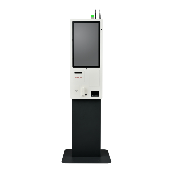
Page 9: Product Views
1.3 Product Views 4G LTE Module Antenna or WiFi Module Antenna (Option) 3-color Status Indicator Camera Module Window True-flat P-CAP Touch Proximity Sensor Lens Printer Receipt Exit EMV Payment Bracket (Option) 2D Barcode Scanner Window (Option) NFC/RFID 2-in-1 Device of MSR/Fingerprint Reader (Option) Sensor (Option) - Page 10 Fan-less System Computer Power Adapter for System Power Adapter for Printer Module 3” Thermal Printer Module 2D Barcode Scanner (Option)
-
Page 11: Introduction Of Pc Box
1.4 Introduction of PC Box I/O Ports of the JK-2410/2710 NFC Module Connector HDMI Port USB 3.0 Port Speaker Connector Hub Board Power Mini DP USB 2.0 Ports Connector Power Button LAN Ports COM2 COM1 9V DC-OUT (RJ50) (RJ50) Power Jack 12V DC-IN Power Jack Micro USB OTG... -
Page 12: I/O Ports Of The Jk-2452/2752
I/O Ports of the JK-2452/2752 Hub Board Power Connector HDMI Port USB 3.0 Ports 9V DC-OUT Mini DP Speaker Connector Power Jack USB 2.0 Ports USB 3.0 Ports COM1 (DB9) Power Button LAN Ports COM3 COM2 (RJ50) (RJ50) 12V DC-IN Power Jack Note1: Mini DP is carried through EDP signal, and it is for specific hub board only. -
Page 13: Introduction Of The Lock
1.5 Introduction of the Lock There are three positions of the lock. Unlock the Printer Door Full Lock Position Unlock the Front Door Open the Printer Door To unlock the printer door, turn the key counterclockwise to around 90 degrees. -
Page 14: Open The Touch Monitor
Open the Touch Monitor To unlock the touch monitor, turn the key counterclockwise to around 180 degrees. See the images below. 180゜ Once the touch monitor is unlocked, you can open the touch monitor through the direction shown in the picture below. -
Page 15: Product Installation
2. Product Installation 2.1 Single Side Standing Installation Package Contents for Single Side Standing Installation Confirm that you have 4 main parts in 3 boxes: Box 1: Single-sided Main System Unit……………………………….x1 True-Flat PCAP Touch Monitor.………..…..………………...x1 Accessory Pack: 2 x M4 Screws for Fixing Touch Monitor and Main System Unit, 2 x M4 Screws for Fixing Door Stopper, User Manual, Paper Roll, 2 keys Box 2:... - Page 16 After installing the main base plate, stand the main stand up. Main Stand Main Base Plate 3. There are four screw holes on the top of the main stand. Place the main system unit on the main stand like the below picture, insert the four M8 hex socket screws into the four screw holes, and then tighten down.
- Page 17 Install the touch monitor kit to the main system unit. Make sure the two hinge of the touch monitor kit insert into the two slots.
- Page 18 Fix the two hinge brackets with the two M4 screws. Put the door stopper behind the top side of the main chassis like the below picture, and fix it with two M4 screws...
- Page 19 Please connect the power cable, display cable, and USB cables refer to the cable routing sticker on the PC box. There is one screw on the cover bracket at the lower portion of the main stand. Remove the cover bracket with one screw.
- Page 20 Remove the rubber cover, pull down the power cord through the cable exit from the main system unit into the main stand, and then pull the power cord out of the cable exit at the lower portion of the main stand. Cable Exit...
-
Page 21: Dual Side Standing Installation
2.2 Dual Side Standing Installation Package Contents for Dual Side Standing Installation Confirm that you have 4 main parts in 3 boxes: Box 1: Dual-sided Main System Unit…………………………………x1 True-Flat PCAP Touch Monitor.………..…………………….x2 Accessory Pack: 4 x M4 Screws for Fixing Touch Monitor and Main System Unit, 4 x M4 Screws for Fixing Door Stopper, User Manual, Paper Roll, 2 keys Box 2:... -
Page 22: Step-By-Step Installation
Step-by-Step Installation Loosen the back cover with two wing nuts. Loosen the back cover with two wing nuts. - Page 23 Carefully remove the back cover from the main system unit. Remove.
- Page 24 Remove the six plugs in the back cover by pressing both sides like the below picture. Press. There are six screw holes both on top side and bottom side. The diameter of each screw hole is 7Ø . 7 Ø screw hole...
- Page 25 Fix the back cover with wall mounting holes on the wall with six screws. Wall Install the main system unit to the back cover, and please note there are four hooks on the back cover. The four hooks need to be stuck into the four slots of the main system.
- Page 27 Fix the back cover with two wing nuts. Fix the back cover with two wing nuts.
- Page 28 Install the touch monitor kit to the main system unit. Make sure the two hinge of the touch monitor kit insert into the two slots.
- Page 29 Fix the two hinge brackets with the two M4 screws. Put the door stopper behind the top side of the main chassis like the below picture, and fix it with two M4 screws...
- Page 30 Please connect the power cable, display cable, and USB cables refer to the cable routing sticker on the PC box. Installation completed.
-
Page 31: Powering On/Off The Kiosk
Push the power button to power the system off. To initiate a forced shutdown, please hold the power button down for 10 seconds. Power Button 3.3 Driver Download If your kiosk system is shipped without OS pre-installed, please download the relevant driver that you need from the Posiflex website (https://download.posiflex.com/en- global/Download/index/driver/Kiosk/CachetJK-2400Series). -
Page 32: Peripherals And Accessories
4. Peripherals and Accessories 4.1 Standard Items Thermal Printer PP-7900JK Overview Power LED Indicator Error LED Indicator Paper-out LED Indicator Feed Button Paper Exit Cover Open Lever Paper Cover Part Names Description Power LED Indicator This indicator turns on when the printer is on. Paper-out LED Indicator This indicator turns on when the paper-out issue occurs. - Page 33 Next, set the paper width by using PP-7900 Series thermal Printer Software Switch Utility for Windows. The software switch utility can be downloaded from the Posiflex’ global website: https://download.posiflex.com/en- global/Download/index/driver/Kiosk/CachetJK-2400Series. To get...
- Page 34 Posiflex’ technical service team. To avoid the paper cover not being locked completely, push the central portion of the paper cover to close. Push Status LED Indicator After powering ON the printer, you can read the printer operation status from the power LED indicator on the printer.
- Page 35 Error LED indicator is flashing Power off the printer; after 10 seconds, power it back on. If the error LED indicator turns on again even after turning the power back on, malfunction may occurs. Contact your dealer or Posiflex’ technical service team.
- Page 36 NV Graphics 256KB (max.) Receive Buffer Windows Driver (APD), OPOS, JavaPOS (Win), Printer Driver CUPS Driver (Linux) Posiflex Uitlity (Android), PP-7900 Utility Software (Windows Desktop), Development Tool (Android SDK), Monitoring Tool (RMS) Blue LED – On = Power LED Indicators...
-
Page 37: Status Indicator Si-100
Graphic UPC-A/E, EAN13/8, ITF, CODE39/93/128, Barcode CODABAR, GS1 DataBar 2D Symbol Printing PDF417, QR code Media Handling Type Thermal roll paper Print Width 80mm paper width: 72 mm 58mm paper width: 54 mm Paper Width 80 or 58 + 0 / - 1 mm Roll Diameter (Max) 80 + 0 / - 1 mm ɸ... -
Page 38: Camera Module Cm-100
Camera Module CM-100 Camera Module CM-100 Basic Specification Camera 1MP wide angle camera Output Interface USB 2.0 interface Input Supply Voltage Vertical 51° Field of View Horizontal 87° Diagonal 102° ※ The product information and specifications are subject to change without prior notice. - Page 39 Trouble Shooting This section contains information about how to solve problems that you may encounter when operating the scanner. If a trouble occurs, please refer to the following diagnostic tips as a mean to solve the trouble. However, before referring to the tips, make sure that the scanner is installed well. If the problem remains, contact your dealer.
-
Page 40: 2-In-1 Device Of Msr/Fingerprint Sensor Mf-2100
Before installing the drivers of the MF-2100 fingerprint/MSR module, after installing the MF-2100 attachment, power on the JK Series kiosk. Installing and Starting the Posiflex USB MSR Manager Before installing the USB MSR Manager, please visit Posiflex official website ( https://download.posiflex.com/en-global/Download/index/driver/Kiosk/CachetJK- ) to download the utility. - Page 41 Please visit Posiflex official website (https://download.posiflex.com/en- global/Download/index/driver/Kiosk/CachetJK-2400Series) to download the virtual COM driver. After downloading it, follow the step-by-step instructive messages to complete the driver installation. After completion of the driver installation, restart your terminal. Installing the Fingerprint Driver Please visit Posiflex official website (https://download.posiflex.com/en-...
-
Page 42: Nfc/Rfid Reader Nr-100
NFC/RFID Reader NR-100 Overview of the NR-100JK (for JK-2410/2710; Android-Based System) NFC Card Reader 9-Pin USB Connector Board Fixing Screw Hole Overview of the NR-100JK (for JK-24x2/27x2; Windows-Based System) NFC Card 5-Pin USB Connector Reader Board Fixing Screw Hole Using the NR-100 Card Reader RFID card reader is located on the lower-right side of the attachment. -
Page 43: Lte Module 4G-100K
PCBA for 4G LTE Module EC25 contains several variants, supporting selected bands & countries with full SIM slot (mini-PCIe module) by request. To get more detailed information of 4G LTE module 4G-100K, please contact the service team of Posiflex. WiFi Module WF-770JK... -
Page 44: Mounting Bracket For Specific Payment Device: Eb Series
Mounting Bracket for Specific Payment Device: EB Series Custom Bracket for Specific Payment Device To do more installation or get more detailed information of EB series, please contact your dealer or the service team of Posiflex.
Need help?
Do you have a question about the JK-24 Series and is the answer not in the manual?
Questions and answers