
Subscribe to Our Youtube Channel
Related Manuals for urmet domus 1036/69


Summary of Contents for urmet domus 1036/69
- Page 1 User Manual IP Camera Gateway Sch./Ref. 1036/69 Please do not connect with PoE port ! Manual version V1.1 Code: SRD-UME1036/69-0815-V1.1...
- Page 2 IS IN YOUR LIFE Preamble Thank you for purchasing Urmet products. This document is the user manual of the U1 Voice system. The user should read this manual thoroughly before operating the products of U1 Voice system. Disclaimer The description, pictures, tables, etc. in this document have been written and verified to the best of knowledge and responsibility of the authors and editors.
-
Page 3: Table Of Contents
IS IN YOUR LIFE Content Chapter 1. Introduction ..................3 1.1 Features ....................3 Chapter 2. Appearance and Interface ............. 4 2.1 Appearance ..................... 4 2.2 Interface..................2 Chapter 3. Connection Diagram ..............5 Chapter 4. Gateway Setting ................6 4.1 Log in gateway..................6 4.2 System Setting .................. -
Page 4: Chapter 1. Introduction
IS IN YOUR LIFE Chapter 1. Introduction The IP camera gateway is a part of the U1 Series building door phone system, it adopts two network card design to manage IP camera in two network segment. The system could perform monitoring function and picture capturing via connecting the device. -
Page 5: Chapter 2. Appearance And Interface
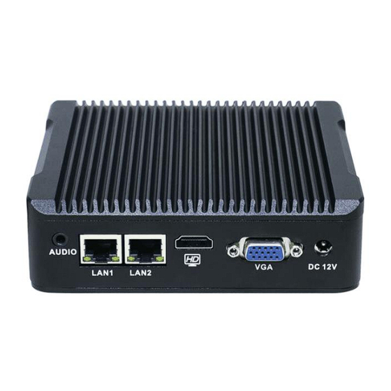
IS IN YOUR LIFE Chapter 2. Appearance and Interface 2.1 Appearance Front view Rear view 1 : Audio interface 2: Network interface LAN1/2 3: HDMI interface 4: VGA interface 5: DC 12V Power interface 6: ON-OFF button 7: 6 USB interfaces 8: COM port... -
Page 6: Chapter 3. Connection Diagram
IS IN YOUR LIFE Chapter 3. Connection Diagram 【 Diagram Description 】 LAN1 must connect to U1 Series phone system, LAN2 should connect to IP camera system. LAN1 port : IP should be fixed as 10.0.0.2 , subnet mask: 255.0.0.0. LAN2 port :... -
Page 7: Chapter 4. Gateway Setting
IS IN YOUR LIFE Chapter 4. Gateway Setting Before using the gateway, please set the IP address for IP cameras, cameras’ IP must be in same network segment as LAN 2's. For related IP camera setting, please find IP camera user manual for reference. 4.1 Log in gateway Set the computer IP address to be 10.0.0.1, subnet mask 255.0.0.0 ;... - Page 8 IS IN YOUR LIFE as below : 4.2.1 Language Setting English or Chinese 4.2.2 Network Setting Set information for LAN2 port interface Automatic acquisition : LAN2 will acquire the interface information according to DHCP. Manual setting : set LAN 2 interface as static information, including IP address, subnet mast and gateway address;...
-
Page 9: Configuration Setting
IS IN YOUR LIFE 4.2.3 Factory data reset Choose Factory Data Reset button to reset the gateway. 4.3 Configuration Setting Choose Configuration Setting to enter in the setting interface,as below: Refresh the device and then choose the unsaved device, the unsaved device will show the IP address on the right side;... -
Page 10: Password Modifying
IS IN YOUR LIFE 【 Notice 】: If fail to set up, please see the sample as reference 4.4 Password Modifying Click Password Modifying to enter in the interface, after inputting the current password, re-input new password and confirm. Interface shown as below:... -
Page 11: Chapter 5. Indoor Station Setting
IS IN YOUR LIFE Chapter 5. Indoor Station Setting Click in the menu of indoor station Camera Setting, input password, then enter in the interface of camera setting. Click the icon on the right, then enter in the interface of camera, shown as below: Input the camera number which is set before , and click Confirm button, the station will be back to the interface of camera setting automatically, and the successful camera number will be shown, as below:... -
Page 12: Chapter 6. Setting Samples
IS IN YOUR LIFE Chapter 6. Setting Samples 6.1 Sample 1 The IP of IP camera is 192.168.2.201, subnet mask : 255.255.255.0. Since the camera’s IP is not at the same network with LAN1, the camera cannot be under LAN1. Enter in the interface of Gateway Setting, to check the network of LAN2, which shown as below: Network for interface LAN2 is 192.168.1, therefore, cannot monitor the... - Page 13 IS IN YOUR LIFE Choose device under Unsaved. To set the device’s number, to remark device’s name; and to input IP camera’s account, password. To click Add, then done, find below photo for reference: The camera is set in the indoor station to realize monitoring and management of the IP camera.
- Page 14 IS IN YOUR LIFE If it pops up the window as below, it means fail to acquire video address. 【 Notice 】 In this case , setting manually is requested.
- Page 15 IS IN YOUR LIFE Enter in the IP camera, to look for the camera video address, which shown as below: 【 Notice 】 Different IP camera owns different video address, please look over at Camera Internal Settings or User Manual. Choose Manual Setting of the Gateway Setting to set up camera, setting interface shown as below:...
- Page 16 IS IN YOUR LIFE Once set up successfully, the interface will show as below: The camera is set in the indoor station to realize monitoring and management of the IP camera.
Need help?
Do you have a question about the 1036/69 and is the answer not in the manual?
Questions and answers