
Subscribe to Our Youtube Channel
Related Manuals for FLIGHTORY SUPER STRINGRAY


Summary of Contents for FLIGHTORY SUPER STRINGRAY
- Page 1 USER MANUAL © 2024 Flightory by Szymon Wójcik All rights reserved. USER MANUAL...
- Page 2 Socials Join Flightory Tech group on Facebook and create community with us. Share progress of your builds. Any suggestions or questions welcome. www.facebook.com/groups/flightory Follow Instagram where I share more footage on a regular basis www.instagram.com/flightory_ USER MANUAL...
- Page 3 General Aircraft Data General data Wingspan 1130mm Wing area 31 dm² Lenght 700mm Center of Gravity 60mm from leading edge (at wing root) 1000-2500g Optimal Cruise Speed 70-90 km/h Airfoil Selig S5020 Root Chord 305mm 271mm Aspect Ratio Wing load 32 - 80 g / dm²...
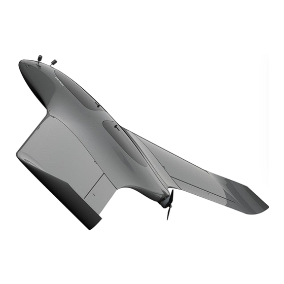
- Page 4 General Aircraft Data The aircraft features a swept wing design with a single pusher motor located at the rear. It is crafted with compactness and modularity in mind. Geometry has been carefully designed and optimized using CFD and real test flights. The wings, as well as the nose of the aircraft, are detachable.
- Page 5 CFD Analysis The geometry has been designed and optimized to achieve maximum efficiency while maintaining the stability of the aircraft. The airfoil used is Selig S5020. With the correct center of gravity set at a distance of 60mm from the leading edge (measured at the wing root), the aircraft maintains a longitudinal stability margin and zero pitching moment at zero angle of attack.
-
Page 6: Exploded View
Exploded View USER MANUAL... - Page 7 Reccomended RC Equipment Reccomended electronics Motor 23XX 1000-1400 KV e.g. link link Propeller 10x5 / 10x6 e.g. link Flight Controller Speedybee/Matek F405 Wing or any other Mavlink FC link link Matek M10Q or similar GPS with compass link Servos Emax ES08MAII Metal Gear or similar link link BlHeli 30-40A...
-
Page 8: Required Accessories
Required Accessories ITEM QUANTITY 12x460mm Carbon Tube (MAIN SPAR) link link 6x680mm Carbon Tube (SECONDARY SPAR) link link 6x350mm Carbon Tube (WING SPAR) link link Thin CA Glue link 20g tube CA Activator link 1 (optional but useful) M3 Threaded Insert (Outer Ø5mm, height 5mm) link M3 screw... - Page 9 PARTS LIST - FUSELAGE PART MATERIAL FUS 1 L/R LW-PLA FUS 2 L/R LW-PLA FUS 3 L/R LW-PLA FUS 4 L/R LW-PLA HATCH FRONT 1 LW-PLA HATCH FRONT 2 LW-PLA HATCH REAR 1 LW-PLA HATCH REAR 2 LW-PLA NOSE LW-PLA NOSE VTX COVER LW-PLA NOSE CLEAN...
- Page 10 PARTS LIST - WINGS PART MATERIAL WING 1 L /R LW-PLA WING 2 L /R LW-PLA WINGTIP 1 L/R LW-PLA WINGTIP 2 L/R LW-PLA AIL 1 L / R LW-PLA AIL 2 L / R LW-PLA SERVO COVER PETG WING ROOT L /R PETG USER MANUAL...
- Page 11 STEP FILES LIST PART AILERON FRONT HATCH MOTOR MOUNT NOSE CLEAN NOSE VTX COVER NOSE REAR HATCH WINGTIP USER MANUAL...
-
Page 12: Print Settings
Print Settings The recommended slicer to use is Ultimaker Cura. All LW-PLA parts, print using the recommended settings detailed on the Flightory website under Print Settings tab. Whether you are using prefoamed or active foaming LW-PLA, you will find settings for both of these filaments there. - Page 13 Print Settings All parts are suitable for printing on any standard printer with a small working area. I printed all parts on a 220 x 220mm area. The settings are just a base that you can change and adjust as needed. The following pages will list my recommended infill settings for each part.
- Page 14 Parts Orientation Important thing is the correct orientation of the printed parts to avoid overhangs, and not have to use supports. Below is the recommended orientation of parts and infill settings. FUS 1 - 3% gyroid infill FUS 2 - 3% gyroid infill USER MANUAL...
- Page 15 Parts Orientation FUS 3 - 3% gyroid infill FUS 4 - 3% gyroid infill USER MANUAL...
- Page 16 Parts Orientation NOSE - 3% gyroid infill + 2 walls NOSE VTX COVER - 3% gyroid infill + 2 walls USER MANUAL...
- Page 17 Parts Orientation HATCH FRONT 1 - 3% gyroid infill HATCH FRONT 2 - 3% gyroid infill USER MANUAL...
- Page 18 Parts Orientation HATCH REAR 1 - 3% gyroid infill HATCH REAR 2 - 3% gyroid infill USER MANUAL...
- Page 19 Parts Orientation WING 1 - 3% gyroid infill WING 2 - 3% gyroid infill USER MANUAL...
- Page 20 Parts Orientation AIL 1 - 3% gyroid infill AIL 2 - 3% gyroid infill USER MANUAL...
- Page 21 Parts Orientation WINGTIP 1 - 3% gyroid infill WINGTIP 2 - 3% gyroid infill USER MANUAL...
- Page 22 Parts Orientation BATTERY PAD- 20% cubic infill + 2 walls MOTOR MOUNT- 20% cubic infill + 2 walls USER MANUAL...
- Page 23 Parts Orientation FUS ROOT - 20% cubic infill WING ROOT - 20% cubic infill USER MANUAL...
- Page 24 NOSE VARIANTS There are 2 variants of the nose. You can choose version with a VTX mounted inside and a 19x19mm FPV camera, or a clean version without any mounts. The VTX mounts on a "shelf" and the available space is sufficient to accommodate any VTX. The nose is fully removable, mounted on four M3 screws.
-
Page 25: Motor Mounts
MOTOR MOUNTS There are two types of motor mounts available, differing in screw spacing. One has a fixed spacing of 19mm, while the other has two screws spaced at 19mm and other two at 16mm. These are the most common dimensions for motors of this class and size. If your motor comes with a metal mount plate, you can omit it and attach the motor directly to the printed motor mount. - Page 26 STEP FILES All files are available in STL format. In addition, some important elements are available in STEP format, which allows easier editing and customization. You can find these files in folders labeled STEP USER MANUAL...
-
Page 27: Fuselage Assembly
Fuselage Assembly Prepare all fuselage segments. Before gluing, you can gently sand the surface of all elements, especially the gluing surfaces. It’s best to use thick CA glue. If you printed the fuselage segments divided to left and right side, simply glue them together also. - Page 28 Fuselage Assembly Prepare parts printed with PET-G or other hard material. Take the BATTERY PAD and paste it in the designated place in the front of the fuselage. Take FUS ROOT and glue with CA to the fuselage in the corresponding places. It’s best to use thick CA glue.
- Page 29 Fuselage Assembly Now take M3 threaded inserts with an outer diameter of 5mm. Glue them into the designated places in the front part of the fuselage. You can use a slightly heated soldering iron for this. Then glue NOSE REINFORCEMENT printed with PETG or other hard material.
- Page 30 Hatches Take the hatches parts and assemble them. Insert LOCK 1 LOCK 2. Assemble it, adding a small spring, and glue it in the designated place. Use a small amount of CA glue, but be careful not to spill the glue and block the lock.
- Page 31 Nose Mount Now you can mount the nose with short M3 screws. If you are using version with VTX, you can put your VTX on the "shelf" and cover it with NOSE VTX COVER and secure the antenna. USER MANUAL...
-
Page 32: Motor Mount
Motor Mount Choose the motor mount that matches your motor and attach it. In the rear part of the fuselage, there are places for M3 threaded inserts on both the top and bottom. Insert the threaded inserts into these spots. Mount the prepared motor in the fuselage, securing it with M3 screws. - Page 33 Fuselage Assembly The fuselage is ready, now it's time to assemble the wings. USER MANUAL...
-
Page 34: Wings Assembly
Wings Assembly Glue the wing segments together. Insert a 6mm carbon tube cut to a length of 350mm. There is no need to glue the tube, just insert it into the designed slot USER MANUAL... - Page 35 Wings Assembly Finally, install the WING ROOT printed from PETG or another rigid material. In the lower part, there are designed slots for regular M3 nuts, which will be responsible for attaching the wings to the fuselage. Insert them there and secure using a few drops of CA glue. Then, glue the root to the wing.
- Page 36 Wings Assembly Insert the aileron using 25x20mm polyester hinges or ones made from another material, similar to the elevator. Then, using a slightly heated soldering iron, attach M3 threaded inserts designed for servo cover mounting. Set the servo so that the control horn protrudes through the opening in the servo cover, glue it in place using hot glue, and cover it.
- Page 37 Wings Assembly Prepare the 12x460mm and 6x680mm carbon tubes, which serve as spars passing through the fuselage. Slide the wings on and route the servo cables into the fuselage. USER MANUAL...
- Page 38 Wings Assembly M3 screws The wing assembly is simple and quick. After pushing the wings against the fuselage, screw in two M3 screws into the designated places. The screws are anchored in PETG-printed material, making the system durable and resistant to repeated wing disassembly USER MANUAL...
- Page 39 Finishing Build Now, organize the rest of the equipment. The remaining space in the fuselage is very spacious and can easily accommodate all the necessary equipment: FC, ESC, GPS, receiver, and more. After placing all the equipment, balance the aircraft by positioning the center of gravity 60mm from the leading edge, measured from the wing- fuselage junction.
-
Page 40: Before Flight
Before Flight Before takeoff, ensure that the direction of the aileron deflection and propeller rotation is correct. For this design, the best way to launch is by throwing it with both hands backward behind your back while holding it wide by the leading edge. The launch technique is demonstrated in the flight videos available on the product page. - Page 41 USER MANUAL...
Need help?
Do you have a question about the SUPER STRINGRAY and is the answer not in the manual?
Questions and answers