
Subscribe to Our Youtube Channel
Related Manuals for Sensit SPOD


Summary of Contents for Sensit SPOD
- Page 1 OPERATION & CONFIGURATION GUIDE READ AND UNDERSTAND INSTRUCTIONS BEFORE USE. 851 Transport Drive • Valparaiso, IN 46383 (USA) Phone: 219.465.2700 • www.GasLeakSensors.com...
-
Page 2: Table Of Contents
CONTENTS WARNINGS ����������������������������������������������������������������������������������������� 3 GENERAL IINFORMATION �������������������������������������������������������������������� 4 DESCRIPTION .......................4 APPLICATIONS ......................4 SENSORS INFORMATION ��������������������������������������������������������������������� 5 CELLULAR SPECIFICATIONS ������������������������������������������������������������������� 6 EXTERIOR FEATURES (FRONT EXTERIOR) ������������������������������������������������ 7 INTERIOR FEATURES (FRONT INTERIOR) ������������������������������������������������ 8 INTERIOR LED INDICATION ������������������������������������������������������������������� 9 DEPLOYMENT GUIDE ���������������������������������������������������������������������������� 10 INCOMING INSPECTION ..................10 QUICK START (WITH COMPUTER) ................11 QUICK START (NO COMPUTER) ................15... -
Page 3: Warnings
All accessories are to be used in an area known to be nonflammable. ⚠ WARNING Do not disassemble the unit or change any parts without training or approval by sensit. If you wish to be certified for repairs, please contact sensit so coordination of training can occur. ⚠ WARNING... -
Page 4: General Iinformation
The SENSIT SPOD has a small footprint and an intuitive interface that makes it easy to use. Therefore, ® it is perfect for applications within the fence line where localized emissions may be present. With its... -
Page 5: Sensors Information
SENSORS INFORMATION SENSOR DETECTION LAMP RANGE ACCURACY RESPONSE METHOD ENERGY (STANDARD) (STANDARD) TIME (EV) (STANDARD) ION - HS 10.6 10 - 3000 ppb* ±20 ppb min or 20% 30-60 sec ION - XF 10.6 0.1 - 30 ppm* ±0.2 ppm min or 30-60 sec ION - 10.0 0.5 - 100 ppm*... -
Page 6: Cellular Specifications
CELLULAR SPECIFICATIONS OVERVIEW PARAMETER Network Technology 4G CAT M1 and Cat 4, and NB-IoT available Carrier AT&T (recommended), Verizon, T-Mobile Transport Layer Internet Layer Application Layer HTTP and MQTT Data Transfer Method HTTP POST or MQTT Topics HTTP Content Type application/x-www-form-urlencoded HTTP Body Field Identifiers &ID, &MODULE, &STAT, &DATA... -
Page 7: Exterior Features (Front Exterior)
EXTERIOR FEATURES (FRONT EXTERIOR) -
Page 8: Interior Features (Front Interior)
INTERIOR FEATURES (FRONT INTERIOR) RED: Connectors BLUE: Ground Planes GREEN: Modem (uFL designators described below). International version: (left to right) M – Primary LTE, G - GPS, and D - secondary or directivity. North American version: (left to right) M – Primary LTE, D - secondary or directivity, and D/G - GPS. -
Page 9: Interior Led Indication
INTERIOR LED INDICATION NOTE: Depending on the revision of circuit board that is in your unit, the identifiers will be different numbers for the LEDs. They are in the same location for each category listed below. Cellular Status: Red LED if failure, Green LED if successful Charging Status: Green LED if Charging Calibration Mode: Solid/Flashing Blue LED in Calibration Sensor Status: Red LED if initialization failure (PID or Weather Station) -
Page 10: Deployment Guide
DEPLOYMENT GUIDE ⚠ WARNING Do not immediately deploy the spod without going through the initial quick start guide. INCOMING INSPECTION ⚠ WARNING Conduct in a controlled setting (laboratory or office). 1. Unpack the sensor unit and check for any physical damage or obstructions at the sensor openings, power button, or communication ports (See images below) 2. -
Page 11: Quick Start (With Computer)
1. Install wireless antenna (if equipped) with cellular or local wireless module. 2. Connect the USB cable between the SPOD and computer to establish the communication link in the terminal software (NOTE: See HARDWARE AND SOFTWARE INSTALLATION GUIDE FOR USB CA- BLE section for more information.) - Page 12 Communication Mode: Cellular, Unlocked Network Selection: LTE Cellular Protocol: CSV Periodic HTTP Always On with TLS Output Data Rate: 60 Cellular Output Ratio: 2 Server Address: http://18.222.146.48/SENSIT/TEST/v1/data/sensor_add.php Access Point Name: zipit.m2m GPS Mode: Disabled PID1 Hours: 763 Sensor Heater: Enabled...
- Page 13 5. Configure the unit to your preferred settings. Configuration mode allows access to configuration set- tings and system settings. The menus are all text-based and easy to follow. The table below contains all the adjustable within the menu. If you are configuring your unit, please see the (DETAILED ROOT MENU INFORMATION) section for additional information.
- Page 14 IF GPS is enabled. 12. Your unit is now ready for deployment. Please see the (DEPLOYMENT INSTRUCTIONS) section for additional and optional setup steps. Make sure to pack and transport the SPOD to the deployment site properly and safely.
-
Page 15: Quick Start (No Computer)
1. Install wireless antenna (if equipped) with cellular or local wireless module. 2. Connect the USB cable between the SPOD and computer to establish the communication link in the terminal software (NOTE: See HARDWARE AND SOFTWARE INSTALLATION GUIDE FOR USB CA- BLE section for more information.) - Page 16 4. Verify that the SD card was detected and initialized with the SD status LEDs NOTE: Depending on the revision of circuit board that is in your unit, the identifiers will be different numbers for the LEDs. They are in the same location for each category listed below. Cellular Status: Red LED if failure, Green LED if successful Charging Status: Green LED if Charging Calibration Mode: Solid/Flashing Blue LED in Calibration Sensor Status: Red LED if initialization failure (PID or MET)
- Page 17 HARDWARE ERROR: The following flash patterns are indicated for 1 minute following startup. This- blink pattern is repeated every 6 seconds and is mirrored on sensor status led inside SPOD housing. 1 blink = PID Lamp 1 > 10000 hours 2 blink = PID Sensor 1 Voltage Error 3 blink = PID Lamp 2 >...
-
Page 18: Deployment Instructions
1. Unpack the SPOD and all accessories that were observed in the inspection. 2. Mount the unit to the desired surface. If you are not mounting to a stationary surface, are using a SENSIT tripod, are using a solar panel, and/or an ultrasonic anemometer is installed; continue with the following steps. -
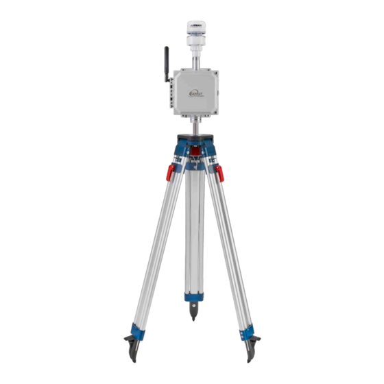
Page 19: Tripod Setup And Installation (Optional)
TRIPOD SETUP AND INSTALLATION (OPTIONAL) 1. Remove protective rubber feet if installing outdoors 2. Install pole on tripod. Pole mounting attachment may differ from image below. 3. Set leg height of tripod and spread legs with a minimum of 30° from perpendicular 4. - Page 20 5. Use the shorter ¼” long screw to attach pole mount to back of SPOD 6. Use the longer 1 ¼” long screw + nut to tighten on pole 7. Tighten sufficiently to prevent rotation 8. Place SPOD as far up as possible on pole to avoid blocking anemometer NOTE: The images below are used for reference.
-
Page 21: Solar Panel Setup & Installation (Optional)
7. Plug cable into SPOD “Power/USB” connection 8. Power on SPOD unit NOTE: Alternative solar mounts and solar panel extension cables can be purchased from Sensit. Please contact Sensit for more information if your application requires an alternative solar mounting setup. -
Page 22: Pole Mount Solar Panel Setup & Installation (Optional)
After the correct angle is set, tighten the 4 bolts fully. 5. Avoid shadowing on panel as much as possible as this will drastically reduce panel output power and efficiency 6. Route cable to SPOD unit 7. Plug cable into SPOD “Power/USB” connection 8. Power on SPOD unit... -
Page 23: Tripod Setup & Anchor Kit Installation (Optional)
(e.g. sandbags, blocks, etc) to prevent the legs from moving or tipping over. SENSIT is not liable for damage due to improper tripod mounting. 4. Screw in earth anchor in the center of tripod footprint and thread ratcheting rope through anchor as shown. -
Page 24: Anemometer (If Installed)
ANEMOMETER (IF INSTALLED) 1. When installing the unit, ensure the alignment notch of the weather sensor is pointing North (see im- age below). Failure to do this will result in error in the wind direction measured by the anemometer. The North direction is indicated with a notch on the ultrasonic anemometer base. Never rotate the anemometer from the top or severe damage will occur. -
Page 25: Usb Output Headings And Description
USB OUTPUT HEADINGS AND DESCRIPTION USB HEADING DESCRIPTION UNITS/FORMAT SPOD Serial Number 1000-63535 DATE Local Date and Time MM/DD/YY HH:MM:SS (24H) PID1 Field 1, Sensor 1 VOC Field 2, Sensor 1 Raw PID2 Field 1, Sensor 2 VOC Field 2, Sensor 2 Raw Temperature °C... -
Page 26: Field 1 (Port Status)
FIELD 1 (PORT STATUS) BIT NUMBER DESCRIPTION 7 (MSB) Port 4: Collected = 1, Not Collected = 0 Port 3: Collected = 1, Not Collected = 0 Port 2: Collected = 1, Not Collected = 0 Port 1: Collected = 1, Not Collected = 0 Port 4: Installed = 1, Not Installed = 0 Port 3: Installed = 1, Not Installed = 0 Port 2: Installed = 1, Not Installed = 0... -
Page 27: Detailed Root Menu Information
CELLULAR: Contains all settings associated with the cellular modem. This is required for communication with any online servers. DEFAULT: Resets all options to the factory default. Not recommended without consulting SENSIT. This will remove all custom settings including cellular information. - Page 28 GPS: “ENABLE” or “DISABLE” the GPS. Depending on the cellular data protocol and output mode, the user may be presented with additional options. If cellular output is disabled or if PERIODIC protocol is selected the GPS mode will default to SINGLE (see below). If cellular output is enabled and MQTT or HTTP protocol are enabled the user can select between the following GPS settings: “CONSTANT”: GPS is always on and fixing position (Highest power draw) “INTERVAL”: GPS turns on at and interval determined by “RATIO”x”ODR”...
-
Page 29: Detailed Cellular Menu Information
“USERPASS” or “AZUREHUB”. To manually configure username and password type “USERPASS”. If using Azure IoT hub, type “AZUREHUB” to send SAS token. The SPOD will parse the relevant connection parameters from the SAS token. The SAS token must have the following parameters to be accepted: SharedAccessSignature sr=<HOSTNAME>%2Fdevices%2F<DEVICEID>... - Page 30 interval of cellular cycles is determined by “ODR” x “RATIO” RATIO: Set the number of required samples between cellular cycles for the “PERIODIC” cellular protocol. This value also influences GPS signal acquisition interval for certain modes. See information of GPS for more info.
- Page 31 Not registered, Searching Registration Denied Unknown Status Registered Successfully, Roaming TLS: Enable or disable TLS encryption for HTTPS or MQTTS. For TLS authentication the user must load a root certificate file for the server on the microSD card. Prior to version 6.00 it was necessary to load a certificate file on the SD prior to enabling TLS.
-
Page 32: Detailed Output Menu Information
ODR: Sets the output data rate of the cellular modem or XBEE wireless device. The USB port will always show data output at 1Hz POLL: Disable streaming over USB/Port and XBEE. SPOD will return data when receiving any character from control device. -
Page 33: Detailed Time Menu Information
DETAILED TIME MENU INFORMATION MENU ITEM DESCRIPTION LOCATION AUTOTIME Enable/Disable Autotime Time Menu TIMEZONE Select LOCAL or UTC Timezone Time Menu Set Date and Time Time Menu AUTOTIME: Autotime sync uses the network time provided by the cellular module if available. For some cellular network SIM card combinations, the provided time can be incorrect and should be disabled to avoid time errors. -
Page 34: Detailed System Menu Information
MET: Enable, disable, or turn MET detection to AUTOMATIC. If MET detection fails it is recommended to enter this menu, disable MET, enable MET, and then restart SPOD. This menu also provides the ability customize the MET filter period to smooth out wind data. -
Page 35: Detailed Sample Menu Information
This requires a 12V valve and is switched with a 3.3V digital output. Valve must be isolated from SPOD. “NONE” is no sampler hooked up. This should be selected if not using a sampler to avoid and initialization error upon startup. “PRESSURE” is configured to allow the valve controller to hook up a pressure sensor to monitor canister pressure and stop sampling at a predefined threshold (-2.5 PSI) and is only relevant for deployments with pressure sensors. -
Page 36: Detailed Trigger Menu Information
If RAW readings are used the threshold will be in mV and if PPB readings are used the threshold will be in ppb. Finally, the SPOD will prompt the user to select a STATIC or DYNAMIC threshold. If a STATIC threshold is selected, the trigger level is absolute with respect to zero. If DYNAMIC threshold is selected, the trigger threshold is with respect the background concentration over a user selectable period ranging from 10 –... -
Page 37: Sensor Maintenance And Calibration
2. After removing the power cable, hook up the USB cable to your computer and the SPOD unit making sure to match up the 4 pins and notch of the cable to the SPOD. NOTE: when plugging in the black USB cable it will reset the SPOD unit. - Page 38 7. Type “Debug” then click on the return key. 8. Type “Exit” then click on the return key. 9. Expose the SPOD to ambient air for a minimum of 3 minutes. NOTE: It is recommended this be con- ducted outside.
- Page 39 11. After the reading is stable, type on the command line “Zero1”. The reading will be zero. 12. Connect the isobutylene calibration gas to the SPOD using the calibration cap. NOTE: Push the cap on fully to minimize the dead air space around the sensor. Be aware the cap is not airtight. The gas will flow out around the sides of the cap during the calibration.
- Page 40 17. Reconnect the power cable to the SPOD. 18. Calibration is now complete. NOTE: If you do not have zero gas you have several options� For firmware version 6.00 and higher, you can apply and OFFSET or ZERO adjust zero level •...
-
Page 41: Sensor Replacement
To replace the sensor follow these steps: 1. Remove the threaded aluminum cap at bottom of SPOD. Retain the threaded cap, screen, and black/ beige plastic spacer. Inspect for cleanliness. Clean all parts in mild detergent and dry if necessary. - Page 42 indicate an error with the sensor. 6. Allow sensor to run for 48 hours before attempting calibration for burn in and stabilization.
-
Page 43: Sensor Firmware Update
HEX file is found inside the folder. 3. Power on SPOD and double click the “FWUPLOAD.BAT” file. A cmd window will open and prompt for a COM port. Type in the com port number determined from coolterm (e.g. “COM34” or “com34”) 4. -
Page 44: Hardware Installation Guide For Avr Programmer
8. Type “UPGRADE”. The SPOD will print out “Upgrade Parameters Sent”. Any addition UPGRADE commands will result in “Upgrade Already Performed” 9. Follow any other instructions provided by Sensit. There is a quickstart instructions text file found in up- loader folder for easy reference. -
Page 45: Hardware And Software Installation Guide For Usb Cable
HARDWARE AND SOFTWARE INSTALLATION GUIDE FOR USB CABLE 1. Download drivers for FTDI Serial Adapter and install drivers https://gasleaksensors.com/products/sensit-spod/ (located in Downloads tab) 2. Open serial terminal program of your choice. CoolTerm is recommended and instructions for using CoolTerm are found below. CoolTerm is available for Windows, Mac, and Linux. CoolTerm can be downloaded for free from here: https://gasleaksensors.com/products/sensit-spod/... - Page 46 b. Select ‘Terminal’ options from list of available options and select ‘Line Mode’ as shown below. Line mode adds a text entry bar at the bottom of the screen that is useful for sending commands to the connected sensor. c. Select ‘Receive’ options from list of available options and check “Ignore Receive Signal Errors”. Selecting this option reduces the possibility of the serial connection closing upon a received serial error such as connecting or disconnecting the cable or power cycling the unit.
- Page 47 b. Click “Save As Default” to change these settings to the default settings when starting the program. If you are running off the CD this option will give you an error as there is no default file. 5. Coolterm can be configured to record all data received over serial. This will be useful for evaluation pur- poses.
-
Page 48: Notes
NOTES __________________________________________________________________________________________ __________________________________________________________________________________________ __________________________________________________________________________________________ __________________________________________________________________________________________ __________________________________________________________________________________________ __________________________________________________________________________________________ __________________________________________________________________________________________ __________________________________________________________________________________________ __________________________________________________________________________________________ __________________________________________________________________________________________ __________________________________________________________________________________________ __________________________________________________________________________________________ __________________________________________________________________________________________ __________________________________________________________________________________________ __________________________________________________________________________________________ __________________________________________________________________________________________ __________________________________________________________________________________________ __________________________________________________________________________________________ __________________________________________________________________________________________ __________________________________________________________________________________________ __________________________________________________________________________________________... - Page 49 NOTES __________________________________________________________________________________________ __________________________________________________________________________________________ __________________________________________________________________________________________ __________________________________________________________________________________________ __________________________________________________________________________________________ __________________________________________________________________________________________ __________________________________________________________________________________________ __________________________________________________________________________________________ __________________________________________________________________________________________ __________________________________________________________________________________________ __________________________________________________________________________________________ __________________________________________________________________________________________ __________________________________________________________________________________________ __________________________________________________________________________________________ __________________________________________________________________________________________ __________________________________________________________________________________________ __________________________________________________________________________________________ __________________________________________________________________________________________ __________________________________________________________________________________________ __________________________________________________________________________________________ __________________________________________________________________________________________...
- Page 50 NOTES __________________________________________________________________________________________ __________________________________________________________________________________________ __________________________________________________________________________________________ __________________________________________________________________________________________ __________________________________________________________________________________________ __________________________________________________________________________________________ __________________________________________________________________________________________ __________________________________________________________________________________________ __________________________________________________________________________________________ __________________________________________________________________________________________ __________________________________________________________________________________________ __________________________________________________________________________________________ __________________________________________________________________________________________ __________________________________________________________________________________________ __________________________________________________________________________________________ __________________________________________________________________________________________ __________________________________________________________________________________________ __________________________________________________________________________________________ __________________________________________________________________________________________ __________________________________________________________________________________________ __________________________________________________________________________________________...
- Page 51 NOTES __________________________________________________________________________________________ __________________________________________________________________________________________ __________________________________________________________________________________________ __________________________________________________________________________________________ __________________________________________________________________________________________ __________________________________________________________________________________________ __________________________________________________________________________________________ __________________________________________________________________________________________ __________________________________________________________________________________________ __________________________________________________________________________________________ __________________________________________________________________________________________ __________________________________________________________________________________________ __________________________________________________________________________________________ __________________________________________________________________________________________ __________________________________________________________________________________________ __________________________________________________________________________________________ __________________________________________________________________________________________ __________________________________________________________________________________________ __________________________________________________________________________________________ __________________________________________________________________________________________ __________________________________________________________________________________________...
-
Page 52: Warranty
WARRANTY Your SENSIT SPOD is warranted to be free from defects in materials and workmanship for a period of ® one year after purchase. If within the warranty period the instrument should become inoperative from such defects the instrument will be repaired or replaced at our option. This warranty covers normal use and does not cover damage which occurs in shipment or failure which results from alteration, tampering, accident, misuse, abuse, neglect or improper maintenance.
Need help?
Do you have a question about the SPOD and is the answer not in the manual?
Questions and answers