
Related Manuals for Wenglor U18T006


Summary of Contents for Wenglor U18T006
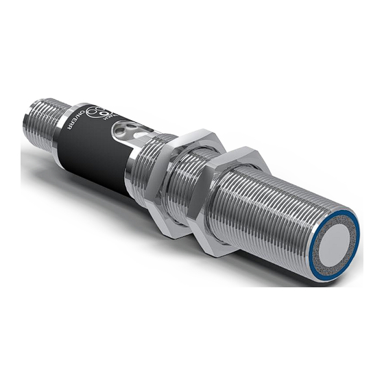
- Page 1 Operating Instructions U18T006 Distance Sensor Translation of the original operating instructions Subject to change without notice Available as PDF file only Version 2.0 www.wenglor.com...
-
Page 2: Table Of Contents
Additional Functions and Settings ........................22 7.2.6 Condition Monitoring Functions ........................... 24 7.2.7 Condition Monitoring/Process Data ........................26 7.3 Pin Functions ..................................26 7.3.1 Input Functions ................................ 27 7.3.2 Output Functions..............................27 Table of Contents | U18T006 ‒ Distance Sensor... - Page 3 8 Maintenance Instructions ............................. 29 9 Proper Disposal ................................30 10 Declarations of Conformity............................31 Table of Contents | U18T006 ‒ Distance Sensor...
-
Page 4: General
The safety precautions and warnings are laid out in accordance with the following principle: SIGNAL WORD Type and source of danger! Possible consequences in the event that the hazard is disregarded. à Measures for averting the hazard. 1 ‒ General | U18T006 ‒ Distance Sensor... -
Page 5: Limitation Of Liability
• wenglor assumes no liability for printing errors or other inaccuracies contained in these operating in- structions unless wenglor was verifiably aware of such errors at the point in time at which the operat- ing instructions were prepared. -
Page 6: Copyrights
• All rights are reserved by wenglor. • Commercial reproduction or any other commercial use of the provided content and information, in particular graphics and images, is not permitted without previous written consent from wenglor. 1 ‒ General | U18T006 ‒ Distance Sensor... -
Page 7: For Your Safety
• The product is not suitable for use in potentially explosive atmospheres. • The product may be used only with accessories supplied or approved by wenglor, or in combination with approved products. A list of approved accessories and combination products can be found at www.wenglor.com on the product detail page. -
Page 8: Personnel Qualifications
Read the operating instructions carefully before using the product. Protect the sensor against contamination and mechanical influences. Approvals and Protection Class IND. CONT. EQ 72HL / E189727 For use in class 2 circuits 2 ‒ For Your Safety | U18T006 ‒ Distance Sensor... -
Page 9: Technical Data
Epoxy resin/glass bubble mixture Degree of Protection IP67 Connection M12 × 1; 4/5-pin Default Settings Technical Data Sensor operating mode Normal Filter Sonic cone default Process data type Outputs and measurement value 3 ‒ Technical Data | U18T006 ‒ Distance Sensor... -
Page 10: Warm-Up Phase
Some technical data depend on the mode set. Depending on the setting, the following data are obtained: Reflex and Through-Beam Mode Filter value Switching frequency in Hz Response time in ms 3 ‒ Technical Data | U18T006 ‒ Distance Sensor... -
Page 11: Sonic Cone Diagrams
Characteristic curves show the position of the center or the front edge of the measured object (Ø 25 mm rod) at the time of switching. Ob = object Sc = sonic cone Standard sonic cone (center of the measured object) 3 ‒ Technical Data | U18T006 ‒ Distance Sensor... -
Page 12: Housing Dimensions
Please note that using multiple ultrasonic sensors can cause reciprocal influence. Housing Dimensions ① = transducer Dimensions specified in mm (1 mm = 0.03937 Inch) Control Panel 01 = switching status indicator 06 = teach-in key 79 = run/error indicator 3 ‒ Technical Data | U18T006 ‒ Distance Sensor... -
Page 13: Complementary Products
Complementary Products wenglor offers you the right connection and mounting technology as well as other accessories for your product. You can find this at www.wenglor.com on the product details page at the bottom. Scope of Delivery • Sensor • Safety precaution •... -
Page 14: Transport And Storage
• Protect the product against exposure to direct sunlight. NOTICE Risk of property damage in case of improper storage! The product may be damaged. à Storage instructions must be complied with. 4 ‒ Transport and Storage | U18T006 ‒ Distance Sensor... -
Page 15: Installation And Electrical Connection
• Wire the sensor in accordance with the connection diagram. • Switch on the supply voltage (see section Technical Data [} 9]). • If using IO-Link, connect the sensor to 18...30 V DC. 5 ‒ Installation and Electrical Connection | U18T006 ‒ Distance Sensor... - Page 16 Safety Input Emitted Light disengageable Grey Safety Output Signal Output Magnet activation White Pink Ethernet Gigabit bidirect. data line (A-D) Input confirmation Green/Yellow Encoder 0-pulse 0-0 (TTL) Contactor Monitoring 5 ‒ Installation and Electrical Connection | U18T006 ‒ Distance Sensor...
-
Page 17: Diagnosis
Device error • Disconnect the sensor from the supply voltage and restart it • Replace the sensor Via IO-Link, it is possible to identify the respective causes precisely by means of condition monitoring. 6 ‒ Diagnosis | U18T006 ‒ Distance Sensor... - Page 18 1. Shut down the machine. 2. Analyze and eliminate the cause of error with the aid of the diagnostics information. 3. If the error cannot be eliminated, please contact wenglor’s support department. 4. Do not operate in case of indeterminate malfunctioning.
-
Page 19: Settings
1. Install the sensor in accordance with the installation instructions. 2. Align the sensor to the background. 3. Press and hold the teach-in key until switching status indicator LED A1 starts to flash. 4. Release the teach-in key after 2 seconds. 7 ‒ Settings | U18T006 ‒ Distance Sensor... -
Page 20: Setting Via Io-Link And Wteach2
To this end, the sensor is connected to a suitable IO-Link master (see product detail page/complementary products). The interface protocol and the IODD can be found at www.wenglor.com in the download area for the respective product. For information on installing and connecting the wTeach2 software and its structure, as well as information on the general functions, see the wTeach2 operating instructions. -
Page 21: Synchronous Mode Of Operation
1. Connect all of the sensors’ pin 5 terminals to each other. 2. Set a sensor as “Multiplex Master”. 3. Set all other sensors as “Multiplex Sub Unit”. 4. An address 1…15 must be assigned to each sensor. 7 ‒ Settings | U18T006 ‒ Distance Sensor... -
Page 22: Additional Functions And Settings
Median filter from the specified number of measured val- ues. The additional interference filter can be used to in- crease measurement reliability in the case of brief inter- ferences in the measured section. Disturbances such as 7 ‒ Settings | U18T006 ‒ Distance Sensor... - Page 23 Read-out of distance values in 1/10 inch for internal temperature compensation or external temperature compensation via the param- eters Millimeter (with external temperature) Output of distance values in mm and input of external temperature via Process Data Out 7 ‒ Settings | U18T006 ‒ Distance Sensor...
-
Page 24: Condition Monitoring Functions
These parameters can be used to set the status messages that are transmitted via the process data. Function Possible settings Default Message 1 See table “Status Messages” Warning signal 7 ‒ Settings | U18T006 ‒ Distance Sensor... - Page 25 In addition, the individual outputs and status messages can be simulated separately from the measured value. INFORMATION Output A1 is used for IO-Link communication in this function and cannot be simulated. Simulation mode ends automatically as soon as the power supply is interrupted. 7 ‒ Settings | U18T006 ‒ Distance Sensor...
-
Page 26: Condition Monitoring/Process Data
"Status messages". Transmit Signal Off Input The sensor’s transmit signal is deactivated as long as the input is activated. The sensor does not supply a measured value and sets the status to 7 ‒ Settings | U18T006 ‒ Distance Sensor... -
Page 27: Input Functions
Transmission signal on as soon as 0 V is applied or the input is opened. 7.3.2 Output Functions The output functions are used to set the physical outputs. Function Possible settings and functions Default PNP/NPN/ 7 ‒ Settings | U18T006 ‒ Distance Sensor... - Page 28 (switching point, warning, error). Warning- and Error Output The error and warning output switches as soon as a fault or warning type has been assigned to it and the condition is fulfilled. 7 ‒ Settings | U18T006 ‒ Distance Sensor...
- Page 29 Cleaning and inspection of the plug connections at regular intervals are advisable. Do not clean the sensor with solvents or cleaning agents that could damage the product. The product must be protected against contamination during initial start-up. 8 ‒ Maintenance Instructions | U18T006 ‒ Distance Sensor...
- Page 30 Proper Disposal wenglor sensoric GmbH does not accept the return of unusable or irreparable products. Respectively valid national waste disposal regulations apply to product disposal. 9 ‒ Proper Disposal | U18T006 ‒ Distance Sensor...
- Page 31 Declarations of Conformity Declarations of conformity can be found on our website at www.wenglor.com in the product’s separate download area. 10 ‒ Declarations of Conformity | U18T006 ‒ Distance Sensor...
Need help?
Do you have a question about the U18T006 and is the answer not in the manual?
Questions and answers