
Subscribe to Our Youtube Channel
Related Manuals for BLAUBERG DVUT 1200 HB EC V.2


Summary of Contents for BLAUBERG DVUT 1200 HB EC V.2
- Page 1 USER'S MANUAL DVUT 1200 HB EC V.2 DVUT 1200 HBE EC V.2 DVUT 1200 HBE2 EC V.2 Single-room air handling unit...
-
Page 2: Table Of Contents
DVUT 1200 HB(E/E2) EC V.2 CONTENTS Safety requirements ..................................2 Safety requirements ..................................2 Purpose ........................................ 4 Delivery set ......................................4 Designation key ....................................4 Technical data ....................................5 Design and operating principle ............................7 Mounting and set-up .................................. 9 Connection to power mains .............................. - Page 3 Ensure that the unit is switched off from the supply mains before removing the guard. Connection to the mains must be made through a disconnecting device, which is integrated into the fixed wiring system in accordance with the wiring rules for design of electrical units, and has a contact separation in all poles that allows for full disconnection under overvoltage category III conditions.
-
Page 4: Purpose
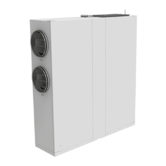
DVUT 1200 HB(E/E2) EC V.2 PURPOSE The unit is designed to ensure continuous mechanical air exchange in houses, offices, hotels, cafes, conference halls, and other utility and public spaces as well as to recover the heat energy contained in the air extracted from the premises to warm up the filtered stream of intake air. -
Page 5: Technical Data
TECHNICAL DATA The unit is designed for indoor application with the ambient temperature ranging from +1 °C up to +40 °C and relative humidity up to 60 % without condensation. In cold, damp rooms, there is a possibility of freezing or condensation inside and outside the casing. In order to prevent condensation on the internal walls of the unit, it is necessary that the surface temperature of the casing is 2-3 °C above the dew point temperature of the transported air. - Page 6 DVUT 1200 HB(E/E2) EC V.2 OVERALL DIMENSIONS [mm] 2106 2000 1110 1900 1951 www.ventilation-system.com...
-
Page 7: Design And Operating Principle
DESIGN AND OPERATING PRINCIPLE UNIT OPERATION LOGIC Heat Recovery mode: warm stale extract air from the room flows into the unit, where it is filtered by the extract filters, then air flows through the heat exchanger and is exhausted outside by the extract fan. Cold fresh air from the outside flows into the unit, where it is cleaned by the supply filters. - Page 8 DVUT 1200 HB(E/E2) EC V.2 DVUT 1200 HBE2 EC V.2 unit design 13 14 15 1, 2 – air dampers; 3 – supply filter; 4 – preheater; 5 – supply fan; 6 – SETUP MODE button; 7 – louver shutters for adjusting supply air direction;...
-
Page 9: Mounting And Set-Up
MOUNTING AND SET-UP READ THE USER'S MANUAL BEFORE INSTALLING THE UNIT While choosing the mounting location provide enough access for maintenance or repair work. Ø 425-450 min 950 The unit is designed for mounting to a horizontal surface adjacent to the wall with the ready-made holes for the air ducts. Lower the supports on the feet of the unit. - Page 10 DVUT 1200 HB(E/E2) EC V.2 Layout of holes for mounting screws (A – M6, B – M8) Remove the protective panels to access the bottom of the unit. At the end of the installation, install the panels in reverse order. Caution: Do not operate the unit with the panels removed.
- Page 11 Secure the sections with screw connections (mounting screws are included in the delivery set). Close the door and install the decorative panel. www.ventilation-system.com...
- Page 12 DVUT 1200 HB(E/E2) EC V.2 , VOC, HUMIDITY SENSOR MOUNTING (NOT INCLUDED IN THE DELIVERY SET) The sensors are installed in the exhaust air duct upstream of the heat exchanger. Before installation, remove the protection plate and remove the extract filter. Install the CO2 and VOC sensors in the respective brackets and connect the connectors to them.
- Page 13 To connect the HV2 humidity sensor, unscrew the screws securing the bracket and remove it. Fix the HV2 humidity sensor with a screw on the bracket and connect the connector. Install the bracket with the sensor to the unit. To connect the DPWC112000 sensor, remove the connector from the cable and connect the cable to the sensor terminal according to the diagram.
- Page 14 DVUT 1200 HB(E/E2) EC V.2 CONDENSATE DRAINAGE The models without a drain pump are equipped with condensate drain pipes. Connect the drain system to the spigots. min 3 mm 1 – drain pipe (Ø 20 mm); 2 – coupling; 3 – L-shaped bend (Ø 20 mm); 4, 6 – connection pipe; 5 – U-trap; 7 – sewage system. A separate drainage system must be connected to each drain pipe.
-
Page 15: Connection To Power Mains
CONNECTION TO POWER MAINS POWER OFF THE POWER SUPPLY PRIOR TO ANY OPERATIONS WITH THE UNIT. THE UNIT MUST BE CONNECTED TO POWER SUPPLY BY A QUALIFIED ELECTRICIAN. THE RATED ELECTRICAL PARAMETERS OF THE UNIT ARE GIVEN ON THE MANUFACTURER’S LABEL. ANY TAMPERING WITH THE INTERNAL CONNECTIONS IS PROHIBITED AND WILL VOID THE WARRANTY. - Page 16 DVUT 1200 HB(E/E2) EC V.2 EXTERNAL CONNECTION DIAGRAM FOR DVUT 1200 HB EC V.2 CCU* +24V 1~230 V/50 Hz (unit with a drain pump) PK1* Boost* 1~230 V/50(60) Hz (unit without a drain pump) EXTERNAL CONNECTION DIAGRAM FOR DVUT 1200 HBE EC V.2, DVUT 1200 HBE2 EC V.2...
-
Page 17: Technical Maintenance
TECHNICAL MAINTENANCE Maintenance operations of the unit are required 3-4 times per year. They include general cleaning of the unit and the following operations: 1. Filter maintenance. Dirty filters increase air resistance in the system and reduce supply air volume. The filters require cleaning not less than 3-4 times per year. -
Page 18: Troubleshooting
DVUT 1200 HB(E/E2) EC V.2 TROUBLESHOOTING IF UNIDENTIFIED NOISES OR ODOURS SHOULD ARISE AND IN CASE OF DEFORMATION OF ELEMENTS, VIBRATION, TERMINATION OF AIR SUPPLY/EXTRACTION OR REDUCED SYSTEM PERFORMANCE, IMMEDIATELY DISCONNECT THE UNIT FROM POWER SUPPLY AND CONTACT THE SELLER FOR THE UNIT DIAGNOSTICS DIAGNOSTICS MUST BE CARRIED OUT BY QUALIFIED SPECIALISTS Problem Possible reasons... -
Page 19: Manufacturer's Warranty
MANUFACTURER’S WARRANTY The product is in compliance with EU norms and standards on low voltage guidelines and electromagnetic compatibility. We hereby declare that the product complies with the provisions of Electromagnetic Compatibility (EMC) Directive 2014/30/EU of the European Parliament and of the Council, Low Voltage Directive (LVD) 2014/35/EU of the European Parliament and of the Council and CE-marking Council Directive 93/68/EEC. - Page 20 DVUT 1200 HB(E/E2) EC V.2 www.ventilation-system.com...
- Page 21 www.ventilation-system.com...
- Page 22 DVUT 1200 HB(E/E2) EC V.2 www.ventilation-system.com...
-
Page 23: Certificate Of Acceptance
CERTIFICATE OF ACCEPTANCE Unit Type Single-room air handling unit Model Serial Number Manufacture Date Quality Inspector’s Stamp SELLER INFORMATION Seller Address Phone Number E-mail Purchase Date This is to certify acceptance of the complete unit delivery with the user’s manual. The warranty terms are acknowledged and accepted. - Page 24 V142-1EN-03...
Need help?
Do you have a question about the DVUT 1200 HB EC V.2 and is the answer not in the manual?
Questions and answers