
Related Manuals for AGCO ACP0940340


Summary of Contents for AGCO ACP0940340
- Page 1 Instruction Manual Applicator lift system ACP0940340 ACP0940350 ACP0940360 April 2024 North America 4205 River Green Parkway, Duluth GA 30096 USA ACX4595570 © AGCO 2023 Original Assembly Instructions English...
- Page 2 You must read this manual before you assemble or use the product. If more assistance is necessary you should speak to your AGCO dealer. This manual is only applicable to the models specified on the front cover.
- Page 3 How to use this manual Color Description Functions Secondary alternative Tertiary component If there are 3 primary components in the illustration, 1 of the 3 components is this color. Special tool Pressure gauges, specified tools Where the special tools or equipment are in an illustration, they are this color.
- Page 4 1 Safety ISO Hydraulic color definition Color Description Color Description Pump flow Suction flow Tank flow No flow Measured flow Reduced flow Intensified fluid Applicator lift system ACX4595570...
- Page 5 1 Safety Safety icons The safety warnings shown in this manual use these icons: DANGER: This is an immediately dangerous situation which, if you ignore it, will cause death or injury. WARNING: This is an immediately dangerous situation which, if you ignore it, will cause death or injury.
- Page 6 Do not change the equipment. An adjustment not specified by the manufacturer can change the function of the machine and cause damage or personal injury. Only use AGCO approved replacement parts. WARNING: To prevent injury and machine damage, you must: •...
- Page 7 1 Safety Waste disposal Incorrect disposal of waste can cause pollution to the environment. Some examples of dangerous waste materials include oil, fuel, coolant, battery chemicals and air-conditioning refrigerant. • Only use an approved container to collect the waste material. Always seal the container after you drain the fluids.
- Page 8 1 Safety Applicator lift system ACX4595570...
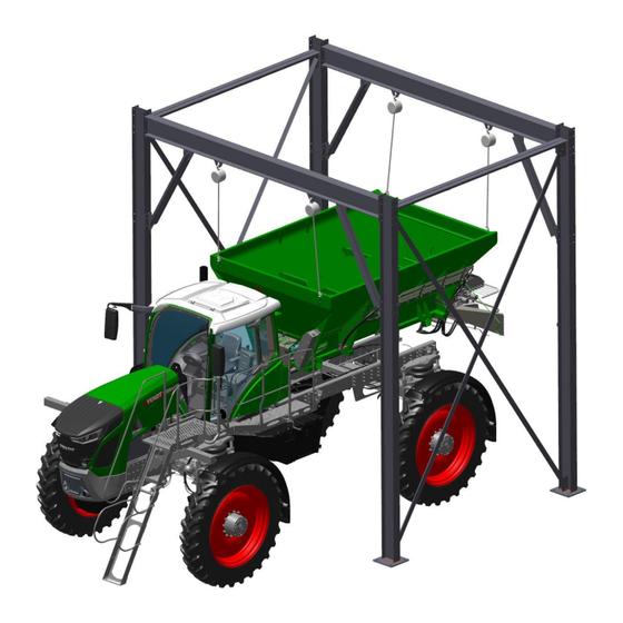
- Page 9 2 Lift equipment installation and applicator lift system usage Liquid system removal : Fendt RG932, RG934/RG934 H , RG937/RG937H WARNING: Heavy components. Incorrect movement of heavy items can cause death or injury. Use the applicable equipment and points to lift or hold the machine and heavy items during procedures.
- Page 10 2 Lift equipment installation and applicator lift system usage 6. NOTE: High clearance machines only. Lift system initially with chain hoists to ensure system is free of chassis. Raise chain hoists evenly to keep load balanced. Lower the machine into the standard clearance position, note that the red stop button on the hydro handle can be used to stop the lowering process if needed.
- Page 11 2 Lift equipment installation and applicator lift system usage 2.2 Liquid system installation : Fendt RG932, RG934/RG934H, RG937/RG937H WARNING: Heavy components. Incorrect movement of heavy items can cause death or injury. Use the applicable equipment and points to lift or hold the machine and heavy items during procedures.
- Page 12 2 Lift equipment installation and applicator lift system usage NOTE: Standard clearance machines. Verify area is clear of people and other obstacles and l ower the chain hoists until the liquid system is on the chassis rails. Lower chain hoists evenly to keep load balanced.
- Page 13 2 Lift equipment installation and applicator lift system usage Dry system removal: Fendt RG932, RG934/RG934H, RG937/RG937H WARNING: Heavy components. Incorrect movement of heavy items can cause death or injury. Use the applicable equipment and points to lift or hold the machine and heavy items during procedures.
- Page 14 2 Lift equipment installation and applicator lift system usage L ift system initially with chain hoists to ensure system is free of chassis. Raise chain hoists evenly to keep load balanced. L ower the machine into the standard clearance position, note that the red stop button on the hydro handle can be used to stop the lowering process if...
- Page 15 2 Lift equipment installation and applicator lift system usage Do not store system suspended from the structure. If the system is to be stored in the structure, it should be lowered onto blocks, removing the load from the hoists. Lower chain hoists evenly to keep load balanced.
- Page 16 2 Lift equipment installation and applicator lift system usage 2.4 Dry system installation : Fendt RG932, RG934/RG934H, RG937/RG937H WARNING: Heavy components. Incorrect movement of heavy items can cause death or injury. Use the applicable equipment and points to lift or hold the machine and heavy items during procedures.
- Page 17 2 Lift equipment installation and applicator lift system usage System removal: Universal Application WARNING: Heavy components. Incorrect movement of heavy items can cause death or injury. Use the applicable equipment and points to lift or hold the machine and heavy items during procedures.
- Page 18 2 Lift equipment installation and applicator lift system usage L ift system initially with chain hoists to ensure system is free of chassis . Raise chain hoists evenly to keep load balanced. Fig. 2 4 Use the chain hoists to lift the system off the chassis until the system is high enough to clear all chassis components.
- Page 19 2 Lift equipment installation and applicator lift system usage Do not store system suspended from the structure. If the system is to be stored in the structure, it should be lowered onto blocks, removing the load from the hoists . Lower chain hoists evenly to keep load balanced.
- Page 20 2 Lift equipment installation and applicator lift system usage 2.6 S ystem installation : Universal Application WARNING: Heavy components. Incorrect movement of heavy items can cause death or injury. Use the applicable equipment and points to lift or hold the machine and heavy items during procedures.
- Page 21 3 Structure dimensions Structure dimensions NOTE: For the double bay structure, the center to center dimension of the 2nd bay is the same as the first, 17 feet 6 in. Fig. 1 Applicator lift system ACX4595570...
- Page 22 4 Foundation requirements Foundation requirements: DANGER: When necessary, you must consider the installation location relative to electrical, fuel, water, and communication utilities. Soil requirements: • All engineered fill shall be as specified in the geotechnical report. Remove existing fill material and replace with engineered granular fill in accordance with the geotechnical report.
- Page 23 4 Foundation requirements Reinforcing steel: • All reinforcing bars shall be new billet steel conforming to the standards of ASTM A615, grade 60. reinforcing bars to be welded shall be ASTM A706. Reinforcement to the epoxy coated shall conform to the standards of ASTM A775. •...
- Page 24 4 Foundation requirements Fig. 2 Approved structure a nchor s : • Hilti Kwik Bolt TZ2 1- 9 - 6.75" hole depth w/ 6.375" min. embedment. - 1" hole size (drill bit size) - Prepare hole per Hilti recommendations • HIT-HY 200 V3 w/ 1"x12" threaded rod (ASTM F1554 Gr36 ) - 9"...
- Page 25 5 Lift system assembly Product assembly - single bay structure DANGER: Alterations must not be made to this equipment. Alterations can produce dangerous situations resulting in serious injuring or death. When necessary, you must consider the installation location relative to electrical, fuel, water, and communication utilities.
- Page 26 5 Lift system assembly Parts list : single bay structure Applicator lift system ACX4595570...
- Page 27 5 Lift system assembly Fastener torque requirements: • Unless otherwise specified, all structure hardware should be tightened to a snug-tight condition. • This does not include the concrete anchors. Follow the anchor manufacturer recommendations. Fastener requirements: • U nless otherwise specified, use ASTM A325 3/4 " x 2 " bolt and nut for all joints during assembly. •...
- Page 28 5 Lift system assembly Install the 2 brackets (1). Do step 3 again for the other end frame. Fig. 2 NOTE: Install the double angle braces with the flat side towards the center as shown. Install 2 sets of double angle braces (1) to the frame as shown.
- Page 29 5 Lift system assembly Lift the end frames into the vertical position: • This can be done either by lifting both at the same time with a crane or large forklift. • Lifting 1 end frame assembly, setting it in place on the foundation, temporarily bracing it in place and then lifting the 2nd end frame assembly into place.
- Page 30 5 Lift system assembly X-brace assembly: 10. Install 2 angles as shown. Install 1 angle on the inside of the mounting plates and the other angle on the outside of the mounting plates. Install square spacer between both angles at the center hole.
- Page 31 5 Lift system assembly 12. Install chain hanger on each column as shown using 1/2" x 1-1/4" flange bolts and 1/2" flange nuts. Fig. 8 Anchoring the structure: 1 3 . NOTE: This procedure is for post-installed anchors, for cast-in-place anchors, see the foundation requirements section.
- Page 32 5 Lift system assembly Parts list : addtional bay structure Applicator lift system ACX4595570...
-
Page 33: Install The 2 Brackets
5 Lift system assembly 5 .2 Product assembly - additional bay structure Before starting the procedure Use the single bay instruction to assemble a single bay. Procedure Note: Assemble these components on the ground. Install the column ( 2 ) onto the top beam (1). Do step 1 for the other top beam. - Page 34 5 Lift system assembly Install the 2 end frames (1) onto the assembled structure. Fig. 13 Install the bracket (1). Do step 8 again for the other end. Fig. 14 10. NOTE: Install the double -angle braces with the flat side towards the center as shown. Install the double-angle braces (1) to the frame as shown.
- Page 35 5 Lift system assembly X-brace assembly: 12. Install 2 angles as shown. Install 1 angle on the inside of the mounting plates and the other angle on the outside of the mounting plates. Install square spacer between both angles at the center hole.
- Page 36 6 Lift equipment installation and applicator lift system usage Chain hoist installation Fig. 1 (A) — Chain hoist location Procedure Install one chain hoist onto each lug on the top beam of the structure. Follow chain hoist recommendations for use, storage, and inspection.
- Page 37 © AGCO Corporation, 2024. All rights reserved. ACX4595570 (English) June 2023...
Need help?
Do you have a question about the ACP0940340 and is the answer not in the manual?
Questions and answers