Table of Contents
Advertisement
Quick Links
Advertisement
Table of Contents

Related Manuals for Technogamma tPell GFX


Summary of Contents for Technogamma tPell GFX
- Page 1 GFX Pellet Stove Controller Revision 45 07/21...
-
Page 2: Table Of Contents
Contents Using the device..................................3 User interface......................................3 Main screen......................................3 Turning on the device..................................4 Set temperature....................................4 Additional screens....................................5 Quick settings...................................... 5 Detailed information..................................5 Errors........................................5 Main menu........................................5 General settings....................................6 Week timer......................................7 Information......................................7 Manual feed......................................7 Events........................................8 Chart........................................ -
Page 3: Using The Device
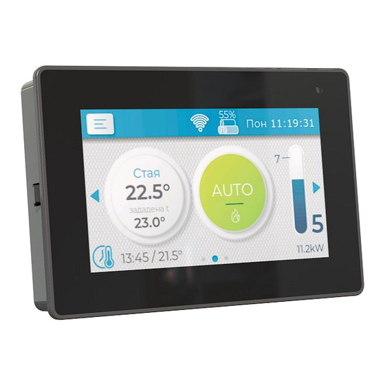
User interface the heated object Temperature set point: desired temperature of the tPell GFX is intuitive and easy to operate, thanks to heated object (room or water) or an icon for the state its color capacitive touch screen. of external thermostat (ON or OFF) -
Page 4: Turning On The Device
Turning on the device Press the mode button to turn the device on or off. Fig 5 Enter code Set temperature Fig 2 Turning on Press the temperature button from the main screen in order to adjust the desired set temperature. On the window that appears, press and hold the button for the selected mode for 3 seconds to con- firm your choice. -
Page 5: Additional Screens
Detailed information ■ Heating – only heating circuit ■ Domestic Hot Water (DHW) ■ Heating + DHW – equal pri- ority for both circuits ■ DHW + Heating – priority for DHW circuit Additional screens Touch and slide left anywhere on the main screen or press to access Quick settings (Fig 8). -
Page 6: General Settings
The menu elements are depicted as tiles with icon and description. Press the desired tile to enter the desired screen. Slide the tile area left / right to move the visible elements and browse the available items. The button returns to previous screen and to main screen if you are in the main menu. -
Page 7: Week Timer
■ Beeper volume – adjust the sound signaliz- Information ation volume, beeper can also be turned off. Week timer Fig 19 Information Detailed records about the device usage: ■ Pellets – counter for the pellets burned Fig 17 Week timer since the last reset. -
Page 8: Events
will be smaller, which will probably lead to failed ig- nition attempt. Events Fig 23 Detailed view tRemote WiFi Fig 21 Events This screen shows the current state of the WiFi List of all the logged errors and events recorded module and if the device is connected to the remote during the operation of the device. -
Page 9: Principle Of Operation
Principle of operation Work mode Depending on the mode, the controller goes through series of states, so it reaches the final state for the mode. Changing the mode, makes the control- ler enter sequence of states, guaranteeing the correct power up or shutdown. The boiler pump is always active, as long as the Fig 25 Service code... -
Page 10: Clean
Clean Shutdown When cleaning, the cleaner mechanism is activ- The fuel is stopped and the fan power is set ac- ated for a fixed time. The cleaning is performed when cording to its shutdown setting. The controller waits the device is powered on and off. for all the remaining fuel to burn out by monitoring the flame detector to go below the set threshold (flue Ignition... -
Page 11: Service Parameters
Service parameters Parameter menus Structure In the table below is a description of all service pa- rameters. They are grouped into sub menus, noted in ■ General table column Menu. ■ Boiler / Ambient fan ■ DHW The fumes fan power is set in percents of the max- imal revolutions, as 100% = Fan Max and 0% = 0 ■... - Page 12 Menu Parameter Description Boiler / Ambient fan Depending on the value of parameter Heating type the menu refers to: • Boiler: water pump, control based on the temperature of H2O • Ambient fan: ambient fan, control based on the temperature of flue gas Min temperature Minimum threshold temperature to turn on the circulation pump.
- Page 13 Menu Parameter Description Level input Level input function: ■ OFF: Not in use ■ Pellet: Level of the pellets inside the bunker ■ Clean: Feedback for the position of the cleaning mechanism. ■ Pressure: Error input for chimney pressure sensor, input E2 Refill Running time of the refill output when a pellet bunker low level is registered.
- Page 14 Menu Parameter Description Restore Power If there is a power break for a period less than the parameter's value, then when the power is restored, the controller returns to Burn state. Otherwise it goes to Shutdown state and the error Power failure is registered if the param- eter Power Failure is set.
- Page 15 Menu Parameter Description Burn Min fan Fan power on minimal work power. Min feeder Feeder time on minimal work power. Max fan Fan power on maximal work power. Max feeder Feeder time on maximal work power. Feeder 2:1 Secondary feeder work time in percent, compared to main feeder. For example if the parameter is set to 200%, then the secondary feeder will work twice longer than the main feeder.
-
Page 16: Additional Menus
The device can be forced to stop, ignoring the con- Additional menus ditions for needed to complete a shutdown procedure. If the device is working, first a transition to Clean Light calibration state is made, as a repetition of Stop Work command switches the device to OFF mode. -
Page 17: Actions
■ Burning stopped: In Burn state, a loss of Temperature Control – Fuzzy Logic al- flame is detected according to the flue gases tempera- ture or light intensity. gorithm ■ Power failure: The power was cut for time The goal of the algorithm is to reach the set temper- exceeding the recovery time. -
Page 18: Connection Diagram
Connection diagram The connection of an external main switch and power supply fuses for L (live) and N (neutral) is man- datory and must be taken into account with the total consumption of all modules! It is mandatory that the housing of the device, as well as all units, are grounded (PE)! Inputs Pt1000 t1 / tFumes Temperature sensor flue gas NTC 10K t2 / tH2O... - Page 19 Fig 29 Connection diagram Connection diagram...
-
Page 20: Assembly
Assembly The control module is mounted using the plastic standoffs provided in the kit. Fig 30 Control module The display is mounted on a flat surface with a rectangular opening measuring 121×79 mm (Fig 31) with a thickness of 1 to 3 mm. Fixing is done by pressing until the periphery rests on the board, with the side teeth locking the box. -
Page 21: Technical Data
■ Visible damages of housing and/or the inner parts of the product ■ Damage caused by lightning storms and/or electric shocks ■ Use in inappropriate conditions (temperature and humidity) Technogamma LTD 4004 Plovdiv, Bulgaria 9N Kuklensko Shose str. fl. 3, office 6 Phone: +359 32 699-240 E-mail: info@technogamma.bg...
Need help?
Do you have a question about the tPell GFX and is the answer not in the manual?
Questions and answers