Table of Contents
Advertisement
Quick Links
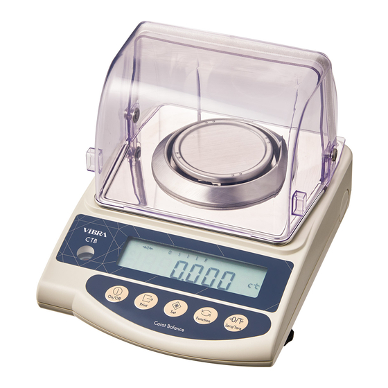
High-Precision Tuning Fork Carat Balance
Operation
•
To ensure safe and proper use of the balance, please read this
manual carefully.
•
After reading this manual, store it in a safe place near the
balance, so you can review it as needed.
SHINKO DENSHI CO., LTD.
CTB703
Manual
IMPORTANT
PRINTED IN JAPAN
310026M01
Advertisement
Table of Contents

Subscribe to Our Youtube Channel
Related Manuals for Vibra CTB703


Summary of Contents for Vibra CTB703
- Page 1 High-Precision Tuning Fork Carat Balance CTB703 Manual Operation IMPORTANT • To ensure safe and proper use of the balance, please read this manual carefully. • After reading this manual, store it in a safe place near the balance, so you can review it as needed.
- Page 2 はくし...
-
Page 3: Preface
PREFACE Thank you for purchasing a High-Precision Tuning Fork Carat Balance model CTB703. This product can measure in carats, which is appropriate for weighing gemstones. Instructions ● The copyright of this document belongs to SHINKO DENSHI CO., LTD. Reprinting or duplicating of all or part of this document without notice shall not be allowed. -
Page 4: Important Notice
Important Notice ・It should be known that this product contains potential danger. And so please be sure to observe this document when installing, operating or servicing this product. ・If the product is used in a manner not specified by the manuals or other accompanying documents, the protection provided by the product may be impaired. -
Page 5: How To Read This Manual
How to read this manual ■Symbols used in this document Understand the meaning of the following symbols and observe the instructions of this document. Symbols Meaning Used for the situation that invites an imminent risk of death or severe injury if proper precautions are not taken. Used for the situation that invites a risk of death or serious injury if proper precautions are not taken. -
Page 6: Bundled Items
Bundled Items Before using the balance, please check that the following items have been included in the package. Should you find any missing parts, please contact your local dealer. (1) Main unit of balance (2) Measurement pan (3) Pan base (4) AC adapter and AC plug set (5) Operation manual (Optional) -
Page 7: Table Of Contents
CONTENTS PREFACE ..........................1 Important Notice ........................2 How to read this manual ......................3 Bundled Items ........................4 CONTENTS ..........................5 1. Prior to use ........................6 1.1 Operating precautions ......................6 1.2 For More Precise Measurements ................... 8 1.2.1 Precautions on the Measuring Room ................8 1.2.2 Precautions on the Measuring Bench ................. -
Page 8: Prior To Use
1. Prior to use 1.1 Operating precautions ■Do not wet the AC adapter. That may cause an electric shock, short-circuiting or failure. ■Do not handle the AC adapter with wet hands. That may cause an electric shock, short-circuiting or failure. ■Do not use the balance in a dusty location. - Page 9 ■Do not handle the balance with wet hands. That may cause short-circuiting or failure. ■Do not use the balance in a wet location. That may cause short-circuiting or failure. ■Do not connect to the AC adapter cord or communication cable with its connector or jack being wet.
-
Page 10: For More Precise Measurements
1.2 For More Precise Measurements To make more accurate measurement, it is necessary to lessen error-causing factors in measurement to the extent possible. Error-causing factors include not only an instrument error and performance of the balance itself but also the nature and condition of a sample, measuring environment (vibration, temperature, humidity, etc.) and the like. -
Page 11: Precautions On The Samples
1.2.3 Precautions on the Samples • In general, synthetic resin- and glass-made samples are high in electric insulation, and so - Static Electricity easily charged electrically. Weighing an electrically charged sample makes the indication value unstable, reducing the reproducibility of the test result. Therefore, neutralise an electrically charged sample before measurement. -
Page 12: Name Of Each Section
2. Name of Each Section 2.1 Main Unit Front View Rear view ① Level ② LCD indicator ③ Operation keys ④ Measurement pan ⑤ Adjuster legs ⑥ AC adapter jack ⑦ RS232C connector ⑧ Windshield ring ⑨ Windshield (5-pin female DIN 41524) -
Page 13: Lcd Indicators And Operating Keys
2.2 LCD Indicators and Operating Keys 2.2.1 Symbols Displayed Display Description gram →0 Zero point indicator Net weight indication when tare is being subtracted Stable state indicator (Indicates that readout is stable.) - Indicates standby status. - Indicates that data being transmitted. momme Indicates that the balance is in processing. -
Page 14: Assembling And Installation
3. Assembling and Installation 3.1 Assembling and installation of the balance First, mount the pan base on the Attach the pan base and place the measurement pan. main unit of the balance and tighten the screw to fix it to the load receptor. -
Page 15: Basic Operations
4. Basic Operations 4.1 Start-Up and Operation Check When the balance has the AC Turning on the power. adapter connected, it enters standby and displays < >. Make sure that there is nothing on the measurement pan and press the [On/Off] key. -
Page 16: Zero-Point Adjustment
4.2 Zero-Point Adjustment Adjusting the indication to zero is called "Zero-point adjustment". Unload the balance. Make sure that nothing is placed on the measurement pan. Execute zero-point adjustment. Press the [Zero/Tare] key. The readout becomes zero, and <→ 0 ←> is displayed (zero-point adjustment). -
Page 17: Weigh The Sample
☆ Weighing only the weight of an added sample Resetting the indication to zero. Press the [Zero/Tare] key. The indication changes to zero and <NET> symbol appears. The balance indicates only the Adding samples to be measured. weight of added samples. 4.4 Weigh the sample Ensure that the balance is in the intended weighing unit. - Page 18 ☆ Key Points of the Procedure ☆ The bar graph shows the current gross load status with respect to the maximum capacity of the balance. The nearer the <F> mark draws, the smaller the measurable weight becomes. *Even when the display currently indicates zero with the tare subtracted, the weight corresponding to the subtracted tare is indicated on the bar.
-
Page 19: Function Setting Mode
5. Function Setting Mode 5.1 Setup and Checking of Functions Press and hold down the [Function] Invoking the function setting mode. key until the indicator changes to <Func>, then release the key. The function setting mode is activated, and the first item, >... -
Page 20: Description Of Functions
5.2 Description of Functions ☆: default factory settings Item Set Value Description 0 Disable 1. b.G. Bar graph display ☆1 Enable 0 Disable This function 1 ±0.5 d automatically sets the 3. A.0 2 ±1.0 d Auto zero tracking zero point exactly to zero ☆3 ±2.0 d to prevent slight deviations. - Page 21 ☆: default factory settings ★1 to ★5: default settings of <81.S.u.> to <85.S.u.> Description Set Value Item ★2 01 gram ★1 02 carat ounce pound ounce troy Setup of weighing 81.S.u. pennyweight Weighing mode unit assignment grain which is switched by 85.S.u.
-
Page 22: Switching Of Weighing Unit
6. Switching of Weighing Unit Pressing the [Function] key switches the weighing unit to “gram”, “carat” and so on. 6.1 Switching Weighing Unit by Key Operation Switching the weighing unit. Press the [Function] key. Each press switches the weighing unit. The weighing unit that is activated when the balance is switched on will be the one that was active when last switched off. - Page 23 Pressing the [Set] key to save the setting. Press the [Set] key to complete the setting. The balance returns to measuring mode. ☆ Key Points of the Procedure ☆ The order of switching units switching by [Function] key is the same as the settings of <81.S.u.> to <85.S.u.>.
-
Page 24: Adjusting The Balance
7. Adjusting the Balance A balance is influenced by the acceleration of gravity, temperature, air pressure, etc. For this reason, you should adjust your balance every time you relocate it. You should also adjust it after a long time of use or when it does not indicate correct values. - Page 25 Calibration of the weighing capacity point. Load the calibration weight on the centre of the measurement pan. The display starts flashing and the balance calibrates the weighing capacity point. Span adjustment is completed. Span adjustment sequence is completed and the indication reverts to measuring mode.
-
Page 26: Input/Output Functions
8. Input/Output Functions 8.1 Terminal Numbers and Functions Terminal Number Signal Input/output Function & remarks External tare-subtraction/zero-point- EXT.TARE Input adjustment This signal is fixed to “HIGH” while the Output balance is powered on. Input Receiving data Output Transmitting data — Signal ground RS232C connector (5-pin female DIN 41524) Take care not to short-circuit the pin 2 (DTR) to the ground. -
Page 27: Connection Between Balance And Peripheral
8.2 Connection between Balance and Peripheral (1) Disconnect the AC adapter of the balance before connecting external devices. (2) Use shielded cable up to 15 m length. ◼◼◼ Sample connection with D-SUB9P ◼◼◼ Balance D-SUB9P DIN5P ◼◼◼ Sample connection with D-SUB25P ◼◼◼ Balance D-SUB25P DIN5P... -
Page 28: Interface Specifications
8.3 Interface Specifications Transmission system: Serial transmission with start-stop synchronisation Transmission rates: 1200/2400/4800/9600 bps. Transmission codes: ASCII codes Signal levels: Compliant with EIA RS-232C +5 to +15 V HIGH level (Data logic 0) -5 to -15 V LOW level (Data logic 1) One-character bit configuration: Start bit: 1 bit Data bit: 8 bits Parity bit: 0/1 bit... - Page 29 (2) Numeric data (D1 to D7/D8: seven or eight characters) - Six-digit numeric format: 7 characters, from D1 to D7 - Seven-digit numeric format: 8 characters, from D1 to D8 D1 to D7/D8 Code Description Numerical value 0–9 0–9 30H–39H 0 is also used to fill the leading portion of value.
-
Page 30: Input Commands
8.5 Input Commands Users can control the balance remotely by transmitting commands from an external device. Two types of control commands are available: Instruction for tare subtraction / zero-point adjustment Setup of output control 8.5.1 Command Transmission Method A command is transmitted to the balance from an external device. Since the data flow (transmission and reception) is stored by a full-duplex system, commands can be transmitted regardless of their data-transmission timing. -
Page 31: Response Output
Setup of output control Code Description Stop output. Output continuously at all times. Output continuously if stable (stop output if unstable). Output once by pressing [Print] key (irrespective of whether the balance is stable or not). Output once when the balance is loaded and stable. The next output for another sample loading is executed once the indication becomes stable at less than or equal to zero by unloading and zero-point adjustment. -
Page 32: Operating The Balance With The Battery
9. Operating the Balance with the Battery This chapter is for the balance equipped with optional built-in rechargeable battery pack. Be sure to use the AC adapter supplied with the balance. A different AC adapter may cause the battery to generate heat or explode. The removal or replacement of the battery by the user is not permitted. -
Page 33: Cleaning The Balance
10. Cleaning the balance Do not wet the AC adapter. (1) Do not remove any parts other than those described in this chapter. If the equipment needs to be dismantled and repaired, e.g. if foreign objects have been introduced inside, contact your local dealer. (2) Do not wash the balance with water. -
Page 34: Troubleshooting
11. Troubleshooting If the trouble persists after following the procedures below, please contact the store you purchased. Symptom Cause Possible remediation → Check that the AC adapter is • The AC adapter is not connected. There is no indication on the display. connected. - Page 35 • The automatic power-off function is → Switch on the power again. For balances with optional built-in activated. Deactivate the Automatic • The battery capacity is low. rechargeable battery power-off function, if pack: necessary. cf. “5.2 Description of The indication Functions”...
-
Page 36: Specifications
Model Scale interval (d) Calibration method Pan size Span adjustment 700 ct 0.001 ct with external CTB703 Ø118 mm 140 g 0.001 g calibration weight (1) Type of weighing sensor: Tuning fork sensor (2) Overload indication: <o-Err> is displayed if the indication exceeds weight capacity by 9 scale intervals... -
Page 37: Functional Specifications
12.3 Functional Specifications Liquid-crystal display (LCD) ......Seven segments (two segments in leading part) Maximum digits indication: seven digits Segment height: 16.5 mm With backlight Operating temperature and humidity ranges .. 5 C to 35 C, 80%rh or less Altitude range ..........2000 m and under Pollution degree .......... -
Page 38: Conversion Table Of Units
13. Conversion Table of Units unit gram carat ounce pound ounce troy pennyweight 1 gram 0.03527 0.00220 0.03215 0.64301 1 carat 0.00705 0.00044 0.00643 0.12860 1 ounce 28.34952 141.74762 0.06250 0.91146 18.22917 1 pound 453.59237 2267.96185 14.58333 291.66667 1 ounce troy 31.10348 155.51738 1.09714... - Page 39 はくし...
- Page 40 はくし...
Need help?
Do you have a question about the CTB703 and is the answer not in the manual?
Questions and answers