
Related Manuals for Carrier 39CS


Summary of Contents for Carrier 39CS
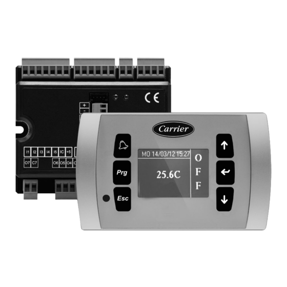
- Page 1 U S E R M A N U A L Advanced control and management system 39CS control 39CS Original document...
- Page 2 Failure to observe the regulations reported in the manual will cause the warranty to lapse immediately. Carrier will not be held liable for any damage deriving from improper use of the machine or failure to observe the regulations reported in this manual and on-board the unit.
-
Page 3: Table Of Contents
CONTENTS 1 - GENERAL CHARACTERISTICS ..............................4 2 - MAIN FUNCTIONS (DEPENDING CONFIGURATION OF THE UNIT PURCHASED) ..............5 3 - USER INTERFACE ..................................6 4 - KEYBOARD ....................................7 4.1 - Main user functions: .................................. 7 4.2 - Turn on / off from the display ..............................8 4.3 - Turn on / off from remote contact .............................. -
Page 4: General Characteristics
1 - GENERAL CHARACTERISTICS The application software is developed for the command and control The control system is composed by: of heat recovery units and compact air handling units with water ■ Power board containing the power supply circuit, the coils or/and with direct expansion coils (without integrated microprocessor system and the connectors for connecting the refrigeration unit). -
Page 5: Main Functions (Depending Configuration Of The Unit Purchased)
2 - MAIN FUNCTIONS (DEPENDING CONFIGURATION OF THE UNIT PURCHASED) ■ Setting of the parameters dedicated to the operation of the ■ Heating resource management: machine protected by password. - Water coil with on/off or modulating type control. - Electric heater with two steps; with monitoring of safety ■... -
Page 6: User Interface
3 - USER INTERFACE Operating mode indication: HEATING Operating mode indication: COOLING Heat recovery antifreeze electric coil in operation Sanification enable For a better understanding we will divide the main screen into two boxes (which will be referred to as left box and right box in the Water valve in operation following) divided by a vertical dividing line (not actually present in the display). -
Page 7: Keyboard
4 - KEYBOARD The user interface keys are 6; the basic functions associated with each key are indicated below. View the list of active alarms and the history. Press for 3 seconds to reset the active alarm. Access to the main menu. Return to the previous mask. -
Page 8: Turn On / Off From The Display
4 - KEYBOARD 4.2 - Turn on / off from the display From the main screen press the “down arrow” Confirm switching on with the Enter key. The machine is operation 4.3 - Turn on / off from remote contact When the open contact symbol appears, it means that the remote ON/ OFF function has been enabled (factory default) and the contact enabled for the function is open. -
Page 9: Time Bands Turn On / Off
4 - KEYBOARD 4.4 - Time bands turn on / off When the “clock” symbol appears, it means that the time bands function has been enabled. The function can be activated by the end user via a menu screen (for information on programming and enabling the time slots, refer to the next chapters). -
Page 10: Screens Available
4 - KEYBOARD 4.6 - Screens available From the main screen, by pressing the “down arrow” key, we can scroll through the entire menu dedicated to machine operation. Turn on Return to previous page Modify the temperature Change summer / winter set (editable) mode (editable) Reading of return or... - Page 11 4 - KEYBOARD Reading of the Supply fan speed recuperator antifreeze reading probe Return fan speed Valve opening reading reading (cold – hot/cold) Heating load Fan reading working hours To modify the values of the editable fields Press enter to modify Modify the value with the arrows Confirm with enter (1) The screens concerning the ventilation control depend on the mode selected during the purchase phase.
-
Page 12: Ventilation Regulation
5 - VENTILATION REGULATION EC - Constant rpm control The speed can be changed from the display; the range depends on the configuration, models with electric heater have higher minimum speeds to prevent their overheating. Modify the value with the arrows Navigate the menu with the arrows;... -
Page 13: Menu
5 - VENTILATION REGULATION EC - Quality control with IAQ (CO /VOC) probe The quality set (CO and VOC) is set in the factory or during the start-up phases by the technician; this cannot be changed from the display (user available screens). What you read in the following screenshots is the current air quality reading. - Page 14 5 - VENTILATION REGULATION Machine configuration menu. Protection password XX Access to this section is for the exclusive use of the manufacturer. Changing these parameters could compromise correct operation Regulation menu Protection password XX The access to this section is for the exclusive use of a specialized technician. Changing these parameters could compromise correct operation.
-
Page 15: Clock Setup Menu
5 - VENTILATION REGULATION 5.3 - Clock setup menu The access to this section allows you the clock and calendar setting; necessary procedure for the correct functioning of the time slots. 5.4 - Menu inputs/ outputs status It is a section dedicated to reading the digital inputs and analog outputs of the controller of both the main and the expansion module (if installed;... -
Page 16: Time Bands Menu
5 - VENTILATION REGULATION 5.5 - Time bands menu In the first 6 screens we have the possibility to set the 3 levels of both temperature and ventilation (in models without flow control) that you would like to alternate in the various time slots. Note: To change values and move in the menu, refer to chapter: NAVIGATE IN THE MENUS AND MODIFY THE PARAMETERS Day to be modified... -
Page 17: Menu Software Version Information
5 - VENTILATION REGULATION To select the time to be changed press the button To change the level of each band You can also set the shutdown To confirm To copy the day just modified press simultaneously To select the day on which copy To confirm 5.6 - Menu software version information Indicates the version of software installed on the machine. -
Page 18: Alarms
6 - ALARMS Any alarms are signaled on the main screen; some of these cause the stop of the machine, others are only for signalling. The reset of the alarm signal can be automatic, i.e. when normal conditions are restored, the signal disappears; or manual, which requires user intervention. -
Page 19: Installer Main Functions
7 - INSTALLER MAIN FUNCTIONS Regulation menu Protection password XX The access to this section is for the exclusive use of a specialized technician. Changing these parameters could compromise correct operation. Serial communication menu Protection password XX The access to this section is for the exclusive use of a specialized technician. The modification of these parameters allows the machine to be inserted in a network for control via BMS 7.1 - Navigate in the menus and modify the parameters... -
Page 20: Communication Parameter List
7 - INSTALLER MAIN FUNCTIONS Parameter Description Range Default Antifreeze alarm delay 0/999 180 s Supply fan pressure set 0/9999 300 Pa Return fan pressure set 0/9999 300 Pa Supply fan flow set 0/9999 1000 m³/h Return fan flow set 0/9999 1000 m³/h Fan regulation band... -
Page 21: Serial Variable List
7 - INSTALLER MAIN FUNCTIONS 7.4 - Serial variable list Address Description ON/OFF unit status General alarm Clogged filter alarm Air flow alarm – supply fan Air flow alarm – return fan Contact alarm – supply fan Contact alarm – return fan Pre-heating electrical heaters alarm Post-heating electrical heaters alarm Recovery-heating electrical heaters alarm... -
Page 22: Read/Write Digital Variables (Coil Status)
7 - INSTALLER MAIN FUNCTIONS 7.5 - Read/write digital variables (coil status) Address Description Unit ON/OFF Summer/winter mode 7.6 - Only read register (input register) Address Description Temperature Room humidity Heat recovery antifreeze temperature Delivery temperature Outdoor temperature Exchanger antifreeze temperature (not used) Temperature set active Humidity set active... -
Page 23: Communication Parameters
7 - INSTALLER MAIN FUNCTIONS 7.8 - Communication parameters Baudrate: 9600 (default); Format: none parity, 8 data-bit, 1 stop-bitù 7.9 - Modbus functions available Address Description Write multiple coil status Write multiple holding register... - Page 24 Please contact your sales representative for more information. Order No: EN7630116-00, 10.2023 - Supersedes order No: New. Carrier, Rte de Thil - 01120 Montluel, France. Manufacturer reserves the right to change any product specifications without notice. Printed in the European Union.
Need help?
Do you have a question about the 39CS and is the answer not in the manual?
Questions and answers