Advertisement
Quick Links
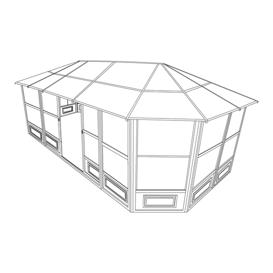
BAAG010GY
12 X 18 SOLARIUM
ASSEMBLY INSTRUCTIO
NS
DO NOT DESTROY THE BOXES UNTIL COMPLETELY ASSEMBLED
PLEASE VERIFY THE CONTENT OF EACH BOX AGAINST THE LIST OF PARTS
Three adults required for assembly
Base Dimensions 12' ½"x18'11"
APPROX.
Largest Dimensions 13'6"x20'4 ½"
Overall Height 110''
(see pg.18)
BAAG010GY.EN
PAGE - 1
Advertisement

Summary of Contents for Erommy BAAG010GY
- Page 1 BAAG010GY 12 X 18 SOLARIUM ASSEMBLY INSTRUCTIO DO NOT DESTROY THE BOXES UNTIL COMPLETELY ASSEMBLED PLEASE VERIFY THE CONTENT OF EACH BOX AGAINST THE LIST OF PARTS Three adults required for assembly Base Dimensions 12’ ½”x18’11” APPROX. Largest Dimensions 13’6”x20’4 ½”...
- Page 2 Consult with your local governing authority / local municipal codes regarding installation of temporary structures before purchase or assembly. Some jurisdictions may require permits for, or otherwise regulate, installation and use. For assistance with assembly, installation, parts, or customer service, contact EROMMY Customer WARNING: ・...
-
Page 3: Maintenance Notes
The product is not warranted in the event it has been improperly anchored. We reserve the right to replace or repair any defective product or parts at our discretion. No change to the unit is allowed. This will void your warranty. BAAG010GY.EN PAGE - 3... - Page 4 #2 Phillips, #2 Robertson Screwdriver (not supplied) Rubber Mallet Various Files 12” piece of wood Based on the location, decide where you would like to position the solarium. Remember the sliding door with “C” shape should be placed on the left side. BAAG010GY.EN PAGE - 4...
- Page 5 (E) between the frame and the door frame. When assembling angled panels (A, B)AND (A,D),you should put the two panels at 135 degree angle, then use the angled connecting pieces (I) and (J) to affix the panels together. BAAG010GY.EN PAGE - 5...
- Page 6 1. Place a bolt (Ww) and washer (Gg) through the top door rail (F) and door frame, and a female bolt (Cc-2) from the other side. Once all are inserted, tighten them all securely. 2. Secure bottom door rail (G), using a bolt (Cc) and washer (Gg). BAAG010GY.EN PAGE -...
- Page 7 180° BAAG010GY.EN PAGE - 7...
- Page 8 4. Then use screw (Oo) to affix the upper door rail end caps (Nn) one at each end of top rail (F). 5. The other side of top rail (F) is same as above st Doors as seen from inside Repeat steps 2 and 3 for the second door. BAAG010GY.EN PAGE - 8...
- Page 9 Make sure that extra hole on bracket remains on the side of angled panel (at the corner). Then screw it to frames with screws (Z). 2) Do not tighten the bolts right away as you may have to adjust the angle when inserting the PC roof panels. BAAG010GY.EN PAGE - 9...
- Page 10 First remove the protective layer from the PC panels, then insert them (Y, Aa, Ll, Qq) between the roof rafters according to the below drawing instructions. Note: the side that had the protective layer should be face down. TOP VIEW BAAG010GY.EN PAGE - 1 0...
- Page 11 After the installation of the middle roof joints complete, insert the bottom PC roof panels (Jj, Kk, Mm, Rr) according to below drawing instructions. They should overlap about two inches under the upper PC roof panels and into the aluminum middle joints. Before A�er TOP VIEW BAAG010GY.EN PAGE - 1 1...
- Page 12 TOP VIEW Step11: Once the installation of the edging complete, start affixing the roof cross bars (T, V, X, Tt) using bolt (Ff). Affix the top cross bars (Uu) onto the roof rafter (L) using bolt (Ff). BAAG010GY.EN PAGE - 12...
-
Page 13: Special Notes
3. Note that this unit is not waterproof. For best protection against rain, close the windows of each frame with the outside window in the center, and the inside window at the top. BAAG010GY.EN PAGE - 13... - Page 14 Suggestions The below mentioned are only suggestions in order to permit drainage, these will vary depending on your flooring – material, flatness and slop BAAG010GY.EN PAGE - 14...
- Page 15 DOOR RAIL RAIL Length 206 cm Length 208 cm 08-163-32 08-138-32 BOTTOM PLASTIC DOOR RAIL STOPPER Length 207 cm 08-140-32 08-139-32 135° ANGLED 135° ANGLED INSIDE OUTSIDE CONNECTOR CONNECTOR Length Length 200 .6 cm .6 cm BAAG010GY.EN PAGE - 14...
- Page 16 ROOF CROSS Length 120.6 Length 94.4 08-153-32 08-154-32 EDGING ROOF CROSS Length 120.6 Length 94.4 cm 08-155 08-156-32 (24 ¼”X42 ¼”) SCREW TOP ROOF LEFT PANEL 08-157 08-158-32 (24 ½”x46 ½”) BOLT TOP ROOF CORNER PANEL BAAG010GY.EN PAGE - 15...
- Page 17 BOTTOM ROOF ROOF PANEL RIGHT PANEL 08-134-32 UPPER DOOR 08-135-32 RAIL END SCREW 08-172 08-170-32 (41 ¼”x42 ¼”) MIDDLE TOP ROOF ROOF JOINT CENTER PANEL 08-171 08-173-32 (41 ¼”x43”) EDGING BOTTOM ROOF CENTER PANEL Length 108 BAAG010GY.EN PAGE - 16...
- Page 18 CORNER KEY ON THE MIDDLE OF THE DOOR (INSTALLED IN Yy) Length 211 cm 11-598-32 11-597-32 HORIZONTAL VERTICAL BAR FOR DOOR FRAME DOOR FRAM Length 200 cm Length 206.14 12-037-32 12-047-32 FEMALE BOLT BOLT (M5*15mm Cc-2 BAAG010GY.EN PAGE - 17...
- Page 19 Note: The dimensions are approximate. BAAG010GY.EN PAGE - 18...
Need help?
Do you have a question about the BAAG010GY and is the answer not in the manual?
Questions and answers