Table of Contents
Advertisement
Quick Links
Advertisement
Table of Contents

Related Manuals for Unist PULSE R

Summary of Contents for Unist PULSE R
- Page 1 Operation Manual...
- Page 2 Questions or part orders: 1-800-253-5462 (US & Canada) 1-616-949-0853 (International) Pulse R™ Operation Manual Copyright © 2023 Unist, Inc. 02/14/2023 V1.2...
- Page 3 This symbol is used to inform you of any potential HAZARD or actions that require your attention. Use of this equipment in a manner other than that specified by Unist, Incorporated may compromise design integrity and become unsafe. The Pulse R system is commercial in ™...
- Page 4 This declaration of conformity is issued under the sole responsibility of the manufacturer. We, the undersigned hereby declare, on behalf of Unist Inc. of Grand Rapids, Michigan that the above-referenced product, to which this declaration relates, is in conformity with the...
-
Page 5: Table Of Contents
Table of Contents System Overview & Operation ............1-3 Introduction ..................1 Specifications ................2 System Layout ................3 Quick Start: Pulse R™ Retrofit Installation ........4-6 Operation ....................7-15 Operation ..................7-9 Locking the Display ..............10 Changing Operation Modes ............11 Operation Mode Details ............12-15... -
Page 6: System Overview & Operation
System Overview & Operation Introduction Thank you for the purchase of your Unist Pulse R™ electronic valve timer. The Pulse R™ was built to combine the fundamentals of a pneumatic pulse generator with a robust electronic program that gives more capability and precise control to the user. The added features create a user-friendly and intuitive device that current and future customers will find easy to implement and use on many systems. -
Page 7: Specifications
System Overview & Operation Specifications Input Power: 24VDC +/-10%, 12 watts max Output: 24VDC, 10 watts max Input Signal: 24VDC (must be on the same ground plane as the input power) Max Input Signal Frequency: 50Hz at 50% duty cycle Valve Output Connection: 11mm/Form B DIN Wafer Connection: 18mm/Form A or 9.4mm/Form C DIN Connector (24VDC ONLY) -
Page 8: System Layout
The system uses a unique wafer design that sandwiches between the existing 24VDC solenoid valve and DIN connector to power the Pulse R™. When the solenoid valve is powered, the wafer draws power from that same source and supplies it to the Pulse R™. -
Page 9: Quick Start: Pulse R™ Retrofit Installation
Quick Start: Pulse R™ Retrofit Installation Step 1: Remove pulse generator Step 2: Detach solenoid coil from Pulse R™ Step 3: Place seals and mount valve... - Page 10 Quick Start: Pulse R™ Retrofit Installation Step 4: Reattach solenoid coil with Pulse R™ STOP Before proceeding, determine if connection method will be via wafer installation or direct wire...
- Page 11 Quick Start: Pulse R™ Retrofit Installation Wafer Installation: Remove DIN connector (3) and mount wafer (2) with gasket (1) to 24VDC solenoid coil. Reattach DIN connector (3) using longer screw provided. Direct Wire Installation: Wire into system according to wiring scheme shown.
-
Page 12: Operation
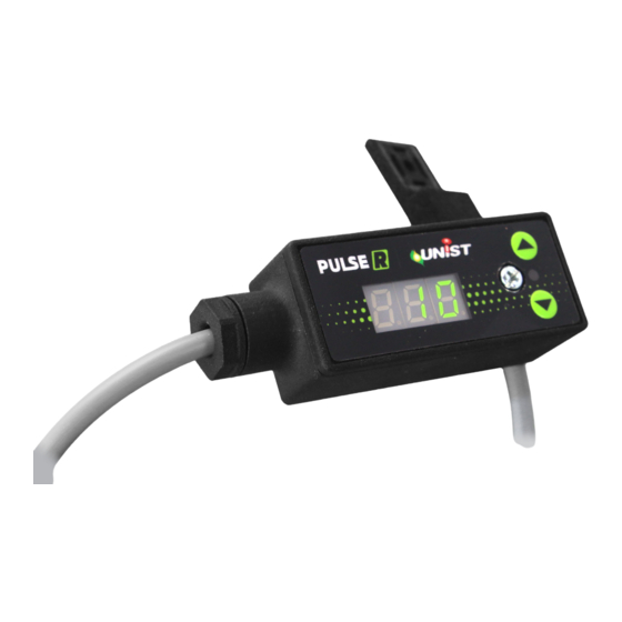
Operation Operation Display Elements When 24VDC power is supplied, the system will display the settings according to the operating mode. Display Figure 3: Display Elements Modes 1 & 2: The system will display the programmed cycles per minute that will be delivered upon power up (mode 1) or an input signal (mode 2). - Page 13 Operation Up and Down Buttons The operator can adjust the set points on the system using the up and down buttons on the right-hand side of the system. Pressing and holding the up or down button will cause the value to rapidly increase or decrease.
- Page 14 F01 = Output Circuit Error An F01 error indicates one of three possibilities: 1. An open circuit is detected. Check to ensure that the Pulse R™ is appropriately connected to valve. 2. A short circuit is detected. Check for any shorts in the system on the output side of the Pulse R™.
-
Page 15: Locking The Display
Operation Locking the Display To prevent accidental changes to settings, the display can be locked by pressing and holding the up and down button buttons at the same time for 3 seconds. The display will show LOC for 1 second, and then show the set point for the mode. -
Page 16: Changing Operation Modes
Operation Changing Operation Modes The Pulse R™ is configured for the desired operating mode at the factory and should only be changed if directed to do so by a Unist representative. To change modes, press and hold both the UP and DOWN buttons while turning on power to the Pulse R™. -
Page 17: Operation Mode Details
Figure 12: Mode 1 Timing Diagram Mode 2 – Repeat cycle on input signal When powered on and the input trigger signal is high, the Pulse R™ output cycles at the rate displayed (indicated in cycles per minute) until the input is removed. The rate can be adjusted from 1 to 250. The duty cycle is automatically set by the Pulse R™. - Page 18 Figure 14: Mode 3 Timing Diagram Mode 4 – Deliver shots on input signal When powered on and the input trigger signal is high, the Pulse R™ output rapidly cycles to deliver the selected number of shots. Once the input is removed, repeat function. In mode 4 the first digit on the display will be flashing “S”.
- Page 19 Operation Mode 5 - CDT (Count and Duration Timer) Mode 5 is a count and duration timer mode. The Pulse R™ will count input signals until the programmed count value (cnt) is reached. Once the count value is reached, it will turn on the output for the programmed duration (dur) of time and reset the counter to zero.
- Page 20 Operation To change the duration value, press and hold the down button for 2 seconds. dur will flash twice and then the value can be changed using the up/down buttons. After 3 seconds of no interaction with the system it will flash dur and save the value. The duration can be adjusted from 0.03 seconds to 250 seconds.
- Page 22 Unist, Inc. 4134 36th Street SE Grand Rapids, MI 49512 USA U.S. & Canada: 800.253.5462 International: 616.949.0853 unist.com Email: salessupport@unist.com PULSEMAN...
Need help?
Do you have a question about the PULSE R and is the answer not in the manual?
Questions and answers