Table of Contents
Advertisement
Quick Links
User's Guide
PM7300-T0/PM5100-T0/
PM3100-T0
XGS-PON SFU with 10G LAN/G-PON SFU with 2.5G LAN/
G-PON SFU with 1G LAN
Default Login Details
LAN IP Address
User Name
Password
Copyright © 2022 Zyxel and/or its affiliates. All Rights Reserved.
http://192.168.0.1
admin
See the device label
Version 5.42 Edition 1, 01/2022
Advertisement
Table of Contents

Subscribe to Our Youtube Channel
Related Manuals for ZyXEL Communications PM7300-TO


Summary of Contents for ZyXEL Communications PM7300-TO
- Page 1 User’s Guide PM7300-T0/PM5100-T0/ PM3100-T0 XGS-PON SFU with 10G LAN/G-PON SFU with 2.5G LAN/ G-PON SFU with 1G LAN Default Login Details Version 5.42 Edition 1, 01/2022 LAN IP Address http://192.168.0.1 User Name admin Password See the device label Copyright © 2022 Zyxel and/or its affiliates. All Rights Reserved.
- Page 2 IMPORTANT! READ CAREFULLY BEFORE USE. KEEP THIS GUIDE FOR FUTURE REFERENCE. This is a series User’s Guide. Screenshots and graphics in this book may differ slightly from your product due to differences in your product firmware or your computer operating system. Every effort has been made to ensure that the information in this manual is accurate.
-
Page 3: Document Conventions
Document Conventions Warnings and Notes These are how warnings and notes are shown in this guide. Warnings tell you about things that could harm you or your device. Note: Notes tell you other important information (for example, other things you may need to configure or helpful tips) or recommendations. -
Page 4: Table Of Contents
Table of Contents Table of Contents Document Conventions ........................3 Table of Contents ..........................4 Part I: User’s Guide.................... 7 Chapter 1 Introducing the PM Device .........................8 1.1 Overview ............................8 1.2 Multi-Gigabit ............................. 8 1.3 Application for the PM Device ....................... 9 1.4 Ways to Manage the PM Device .................... - Page 5 Table of Contents 5.1 Overview ............................26 5.1.1 What You Can Do in this Chapter ..................26 5.1.2 Before You Begin ........................26 5.2 Broadband Settings ........................26 5.2.1 Add/Edit Internet Connection ..................... 27 Chapter 6 Home Networking ..........................29 6.1 Overview ............................29 6.1.1 What You Need To Know .....................
- Page 6 Table of Contents 11.1 Overview ............................44 11.2 The User Account Screen ......................44 11.2.1 The User Account Add/Edit Screen .................. 45 Chapter 12 Remote Management ........................47 12.1 Overview ............................47 12.2 The Remote Management Screen ..................... 47 Chapter 13 Time Settings............................49 13.1 Time Settings Overview ........................
-
Page 7: Part I: User's Guide
User’s Guide... -
Page 8: Introducing The Pm Device
H A P T E R Introducing the PM Device 1.1 Overview This chapter introduces the main features and applications of the PM Devices. The PM3100-T0 is a G-PON (Passive Optical Network) modem with one 1 Gbps Multi-Gigabit Ethernet LAN port. The PM5100-T0 is a G-PON modem with one 2.5 Gbps Multi-Gigabit Ethernet LAN port. The PM7300-T0 is a XGS- PON modem with one 10 Gbps Multi-Gigabit Ethernet LAN port. -
Page 9: Application For The Pm Device
Chapter 1 Introducing the PM Device Multi-Gigabit (IEEE 802.3bz) solves these problems by additionally supporting 2.5 Gigabit and 5 Gigabit Ethernet connections over Cat 5e and higher Ethernet cables. Multi-Gigabit ports are also backward compatible with 100 Mbps and 1 Gigabit ports. See the following table for the cables required and distance limitation to attain the corresponding speed. -
Page 10: Ways To Manage The Pm Device
Chapter 1 Introducing the PM Device Figure 2 Internet Access Application: Wired Connection 1.4 Ways to Manage the PM Device Use any of the following methods to manage the PM Device. • Web Configurator. This is recommended for management of the PM Device using a (supported) web browser. -
Page 11: Chapter 2 Hardware
H A P T E R Hardware This chapter describes the top panel LED and side panel ports of the PM Devices. 2.1 Top Panels The following show the LEDs on the PM Devices. Figure 3 PM7300-T0 Top Panel PM7300-T0/PM5100-T0/PM3100-T0 User’s Guide... - Page 12 Chapter 2 Hardware Figure 4 PM5100-T0 Top Panel Figure 5 PM3100-T0 Top Panel PM7300-T0/PM5100-T0/PM3100-T0 User’s Guide...
-
Page 13: Leds (Lights)
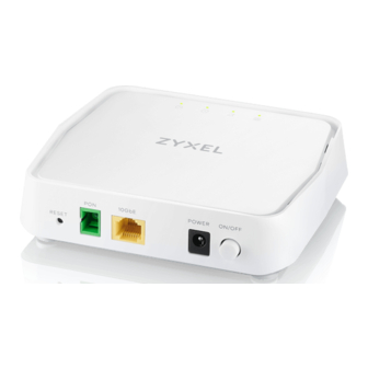
Chapter 2 Hardware 2.1.1 LEDs (Lights) The LED indicators are located on the top panel. Table 3 LED Behavior COLOR STATUS DESCRIPTION Power Green The PM Device is ready for use. Blinking The PM Device is booting. The PM Device is not receiving power. There is a system failure. - Page 14 Chapter 2 Hardware Figure 7 PM5100-T0 Side Panel Figure 8 PM3100-T0 Side Panel The following table describes the items on the side panel. Table 4 Side Panel Ports and Buttons LABELS DESCRIPTION RESET Press for more than 5 seconds to restore the PM Device to its factory default settings. Connect the PM Device to the Internet using a fiber optic cable.
-
Page 15: Reset Button
Chapter 2 Hardware Table 4 Side Panel Ports and Buttons (continued) LABELS DESCRIPTION 10GbE Connect the PM7300-T0 to an Ethernet device such as a network switch, NAS or server for fiber- (PM7300-T0) speed internet access. The maximum transmission speed on the LAN is 10 Gbps. Connect to a computer for initial configuration. - Page 16 Chapter 2 Hardware Figure 11 PM3100-T0 Reset Button Make sure the PM Device is connected to power and the POWER LED is on. Using a thin item, press the RESET button for more than 5 seconds. PM7300-T0/PM5100-T0/PM3100-T0 User’s Guide...
-
Page 17: The Web Configurator
H A P T E R The Web Configurator 3.1 Overview The Web Configurator is an HTML-based management interface that allows easy system setup and management via Internet browser. Use a browser that supports HTML5, such as Internet Explorer 11, Microsoft Edge, Mozilla Firefox, or Google Chrome. - Page 18 Chapter 3 The Web Configurator The following screen displays if you have not yet changed your password. Enter a new password, re- enter it to confirm and click Apply. Figure 13 Change Password Screen The Connection Status screen appears. Use this screen to view basic Internet access connection. Figure 14 Connection Status PM7300-T0/PM5100-T0/PM3100-T0 User’s Guide...
-
Page 19: Web Configurator Layout
Chapter 3 The Web Configurator 3.2 Web Configurator Layout Figure 15 Screen Layout As illustrated above, the main screen is divided into these parts: • A - Title bar: this shows the Zyxel logo and device model name. • B - Menu: click this to show the navigation panel and side bar. •... - Page 20 Chapter 3 The Web Configurator Figure 16 Side Bar The icons provide the following functions. Table 5 Web Configurator Icons in the Title Bar ICON DESCRIPTION Theme: Click this icon to select a color that you prefer and apply it to the Web Configurator. Language: Select the language you prefer.
-
Page 21: Navigation Panel
Chapter 3 The Web Configurator 3.2.2 Navigation Panel Click the menu icon ( ) to show the navigation panel. Use the menu items on the navigation panel to open screens to configure PM Device features. The following tables describe each menu item. Table 6 Navigation Panel Summary LINK FUNCTION... -
Page 22: Widget And Check Icon
Chapter 3 The Web Configurator Figure 17 Navigation Panel 3.2.4 Widget and Check Icon Click the Widget icon ( ) in the lower left corner to arrange the screen order. The following screen appears. Select a block and hold it to move around. Click the Check icon ( ) in the lower left corner to save the changes. - Page 23 Chapter 3 The Web Configurator Figure 18 Check Icon PM7300-T0/PM5100-T0/PM3100-T0 User’s Guide...
-
Page 24: Chapter 4 System Info
H A P T E R System Info 4.1 Overview After you log into the Web Configurator, the System Info screen appears. This shows basic information about the PM Device. You can expand this screen to view the WAN/LAN interface status and LAN IP address information. 4.2 The System Info Screen Use this screen to view the basic system information of the PM Device. - Page 25 Chapter 4 System Info Figure 20 System Info: Detailed Information Each field is described in the following table. Table 7 System Info: Detailed Information LABEL DESCRIPTION Host Name This field displays the PM Device system name. It is used for identification. Model Name This shows the model number of your PM Device.
-
Page 26: Chapter 5 Broadband
H A P T E R Broadband 5.1 Overview This chapter discusses the PM Device’s Broadband screens. Use these screens to configure your PM Device for Internet access. A WAN (Wide Area Network) connection is an outside connection to another network or the Internet. It connects your private networks, such as a LAN (Local Area Network) and other networks, so that a computer in one location can communicate with computers in other locations. -
Page 27: Add/Edit Internet Connection
Chapter 5 Broadband Figure 22 Network Setting > Broadband The following table describes the labels in this screen. Table 8 Network Setting > Broadband LABEL DESCRIPTION Add New WAN Click this button to create a new connection. Interface This is the index number of the entry. Name This is the service name of the connection. - Page 28 Chapter 5 Broadband Bridge Mode Click the Add New WAN Interface in the Network Setting > Broadband screen or the Edit icon next to the connection you want to configure. The following example screen displays when you select Bridge mode. Figure 23 Network Setting >...
-
Page 29: Chapter 6 Home Networking
H A P T E R Home Networking 6.1 Overview A Local Area Network (LAN) is a shared communication system to which many networking devices are connected. It is usually located in one immediate area such as a building or floor of a building. Use the Home Networking screens to help you configure the LAN IP addresses. - Page 30 Chapter 6 Home Networking Click Apply to save your settings. Figure 24 Network Setting > Home Networking The following table describes the fields on this screen. Table 10 Network Setting > Home Networking LABEL DESCRIPTION LAN IP Setup IP Address Enter the LAN IPv4 address you want to assign to your PM Device in dotted decimal notation, for example, 192.168.0.1 (factory default).
-
Page 31: Chapter 7 Certificates
H A P T E R Certificates 7.1 Certificates Overview The PM Device can use certificates (also called digital IDs) to authenticate users. Certificates are based on public-private key pairs. A certificate contains the certificate owner’s identity and public key. Certificates provide a way to exchange public keys for use in authentication. - Page 32 Chapter 7 Certificates Figure 25 Security > Certificates > Local Certificates The following table describes the labels in this screen. Table 11 Security > Certificates > Local Certificates LABEL DESCRIPTION Private Key is Select the check box and enter the private key into the text box to store it on the PM Device. protected by a The private key should not exceed 63 ASCII characters (not including spaces).
-
Page 33: Create Certificate Request
Chapter 7 Certificates 7.3.1 Create Certificate Request Click Security > Certificates > Local Certificates and then Create Certificate Request to open the following screen. Use this screen to have the PM Device generate a certification request. To create a certificate signing request, you need to enter a common name, organization name, state/province name, and the two-letter country code for the certificate. - Page 34 Chapter 7 Certificates certification authority. The Private Key serves as your digital signature for authentication and must be safely stored. Figure 27 Certificate Request: View The following table describes the fields in this screen. Table 13 Certificate Request: View LABEL DESCRIPTION Name This field displays the identifying name of this certificate.
-
Page 35: Trusted Ca
Chapter 7 Certificates 7.4 Trusted CA Click Security > Certificates > Trusted CA to open the following screen. This screen displays a summary list of certificates of the certification authorities that you have set the PM Device to accept as trusted. The PM Device accepts any valid certificate signed by a certification authority on this list as being trustworthy;... -
Page 36: Import Trusted Ca Certificate
Chapter 7 Certificates Figure 29 Trusted CA: View The following table describes the fields in this screen. Table 15 Trusted CA: View LABEL DESCRIPTION Name This field displays the identifying name of this certificate. This read-only text box displays the certificate in Privacy Enhanced Mail (PEM) format. PEM uses base 64 to convert the binary certificate into a printable form. - Page 37 Chapter 7 Certificates Figure 30 Trusted CA: Import Certificate The following table describes the fields in this screen. Table 16 Trusted CA: Import Certificate LABEL DESCRIPTION Certificate File Click Browse or Choose File and select the certificate you want to upload. Path Choose File/ Click this button to find the certificate file you want to upload.
-
Page 38: Chapter 8 Log
H A P T E R 8.1 Overview The Web Configurator allows you to choose which categories of events and/or alerts to have the PM Device log and then display the logs or have the PM Device send them to an administrator (as e-mail) or to a syslog server. - Page 39 Chapter 8 Log Table 17 System Monitor > Log > System Log (continued) LABEL DESCRIPTION Time This field displays the time the log was recorded. Facility The log facility allows you to send logs to different files in the syslog server. Refer to the documentation of your syslog program for more details.
-
Page 40: Chapter 9 Traffic Status
H A P T E R Traffic Status 9.1 Traffic Status Overview Use the Traffic Status screens to look at the network traffic status and statistics of the WAN/LAN interfaces and NAT. 9.1.1 What You Can Do in this Chapter •... -
Page 41: Lan Status
Chapter 9 Traffic Status The following table describes the fields in this screen. Table 18 System Monitor > Traffic Status > WAN LABEL DESCRIPTION Refresh Interval Select how often you want the PM Device to update this screen. Connected This shows the name of the WAN interface that is currently connected. Interface Packets Sent Data... - Page 42 Chapter 9 Traffic Status Figure 33 System Monitor > Traffic Status > LAN The following table describes the fields in this screen. Table 19 System Monitor > Traffic Status > LAN LABEL DESCRIPTION Refresh Interval Select how often you want the PM Device to update this screen. Interface This shows the LAN or wireless LAN interface on the PM Device.
-
Page 43: Chapter 10 System
H A P T E R System 10.1 Overview On the System screen, you can name your PM Device (Host) and give it an associated domain name for identification purposes. 10.2 The System Screen Click Maintenance > System to open the following screen. Assign a unique name to the PM Device so it can be easily recognized on your network. -
Page 44: Chapter 11 User Account
H A P T E R User Account 11.1 Overview In the User Account screen, you can view the settings of the “admin” and other user accounts that you use to log in the PM Device. 11.2 The User Account Screen Click Maintenance >... -
Page 45: The User Account Add/Edit Screen
Chapter 11 User Account Table 21 Administrator/User privilege differences LINK ADMINISTRATOR USER Certificates System Monitor Traffic Status Maintenance System User Account Remote Management Time Log Setting Firmware Upgrade Backup Restore Reboot The following table describes the labels on this screen. Table 22 Maintenance >... - Page 46 Chapter 11 User Account Figure 36 Maintenance > User Account > Edit The following table describes the labels on this screen. Table 23 Maintenance > User Account > Add/Edit LABEL DESCRIPTION Active Click to enable (switch turns blue) or disable (switch turns gray) the user account. This field is grayed out if you are editing the logged-in account.
-
Page 47: Chapter 12 Remote Management
H A P T E R Remote Management 12.1 Overview Remote management controls which services can access the PM Device in the interfaces you select. 12.2 The Remote Management Screen Use this screen to configure which services can access the PM Device and which interfaces can allow them. - Page 48 Chapter 12 Remote Management Table 24 Maintenance > Remote Management (continued) LABEL DESCRIPTION Apply Click Apply to save your changes back to the PM Device. Cancel Click Cancel to restore your previously saved settings. PM7300-T0/PM5100-T0/PM3100-T0 User’s Guide...
-
Page 49: Chapter 13 Time Settings
H A P T E R Time Settings 13.1 Time Settings Overview This chapter shows you how to configure system related settings, such as system date and time. This chapter shows you how to configure system related settings, such as system time, password, name, the domain name and the inactivity timeout interval. - Page 50 Chapter 13 Time Settings Figure 38 Maintenance > Time The following table describes the fields in this screen. Table 25 Maintenance > Time LABEL DESCRIPTION Current Date/Time Current Time This displays the time of your PM Device. Each time you reload this screen, the PM Device synchronizes the time with the time server. Current Date This displays the date of your PM Device.
- Page 51 Chapter 13 Time Settings Table 25 Maintenance > Time (continued) LABEL DESCRIPTION First – Fifth Time Select an NTP time server from the drop-down list box. Server Address Otherwise, select Other and enter the IP address or URL (up to 29 extended ASCII characters in length) of your time server.
-
Page 52: Chapter 14 Log Setting
H A P T E R Log Setting 14.1 Overview You can configure where the PM Device sends logs and which logs and/or immediate alerts the PM Device records in the Logs Setting screen. 14.2 The Log Settings Screen To change your PM Device’s log settings, click Maintenance > Log Setting. The screen appears as shown. - Page 53 Chapter 14 Log Setting Table 26 Maintenance > Log Setting (continued) LABEL DESCRIPTION Apply Click Apply to save your changes. Cancel Click Cancel to restore your previously saved settings. PM7300-T0/PM5100-T0/PM3100-T0 User’s Guide...
-
Page 54: Chapter 15 Firmware Upgrade
H A P T E R Firmware Upgrade 15.1 Overview This chapter explains how to upload new firmware to your PM Device. You can download new firmware releases from your nearest Zyxel FTP site (or www.zyxel.com) to use to upgrade your device’s performance. - Page 55 Chapter 15 Firmware Upgrade The following table describes the labels on this screen. After you see the firmware updating screen, wait two minutes before logging into the PM Device again. Table 27 Maintenance > Firmware Upgrade LABEL DESCRIPTION Upgrade Firmware Restore Default Click the check box to have the PM Device automatically reset itself after the new firmware is Settings After...
-
Page 56: Chapter 16 Backup/Restore
H A P T E R Backup/Restore 16.1 Overview The Backup/Restore screen allows you to backup and restore device configurations. You can also reset your device settings back to the factory default. 16.2 The Backup/Restore Screen Click Maintenance > Backup/Restore. Information related to factory defaults, backup configuration, and restoring configuration appears on this screen, as shown below. - Page 57 Chapter 16 Backup/Restore Figure 42 Maintenance > Backup/Restore Backup Configuration Backup Configuration allows you to back up (save) the PM Device’s current configuration to a file on your computer. Once your PM Device is configured and functioning properly, it is highly recommended that you back up your configuration file before making configuration changes.
-
Page 58: The Reboot Screen
Chapter 16 Backup/Restore Restore Configuration Restore Configuration allows you to upload a new or previously saved configuration file from your computer to your PM Device. Table 28 Restore Configuration LABEL DESCRIPTION File Path Type in the location of the file you want to upload in this field or click Browse to find it. Browse Click this to find the file you want to upload. - Page 59 Chapter 16 Backup/Restore Figure 44 Maintenance > Reboot PM7300-T0/PM5100-T0/PM3100-T0 User’s Guide...
-
Page 60: Chapter 17 Troubleshooting
H A P T E R Troubleshooting This chapter offers some suggestions to solve problems you might encounter. The potential problems are divided into the following categories. • Power, Hardware Connections, and LEDs • PM Device Access and Login • Internet Access 17.1 Power, Hardware Connections, and LEDs The PM Device does not turn on. -
Page 61: Pm Device Access And Login
Chapter 17 Troubleshooting 17.2 PM Device Access and Login I forgot the IP address for the PM Device. The default LAN IP address is 192.168.0.1. If you changed the IP address and have forgotten it, you might get the IP address of the PM Device by looking up the IP address of the default gateway for your computer. -
Page 62: Internet Access
Chapter 17 Troubleshooting If the problem continues, contact the network administrator or vendor, or try one of the advanced suggestions. Advanced Suggestions • Make sure you have logged out of any earlier management sessions using the same user account even if they were through a different interface or using a different browser. •... - Page 63 Chapter 17 Troubleshooting Check the hardware connections, and make sure the LEDs are behaving as expected. See the Quick Start Guide and Section 2.1.1 on page The PON LED is off if the optical transceiver has malfunctioned or the fiber cable is not connected or is broken or damaged enough to break the PON connection.
-
Page 64: Part Ii Appendices
Appendices... -
Page 65: Appendix A Customer Support
In the event of problems that cannot be solved by using this manual, you should contact your vendor. If you cannot contact your vendor, then contact a Zyxel office for the region in which you bought the device. For Zyxel Communications offices, see https://service-provider.zyxel.com/global/en/contact-us for the latest information. - Page 66 • Zyxel Singapore Pte Ltd. • http://www.zyxel.com.sg Taiwan • Zyxel Communications Corporation • https://www.zyxel.com/tw/zh/ Thailand • Zyxel Thailand Co., Ltd • https://www.zyxel.com/th/th/ Vietnam • Zyxel Communications Corporation-Vietnam Office • https://www.zyxel.com/vn/vi Europe Belarus • Zyxel BY • https://www.zyxel.by Bulgaria • Zyxel България • https://www.zyxel.com/bg/bg/...
- Page 67 Appendix A Customer Support Czech Republic • Zyxel Communications Czech s.r.o • https://www.zyxel.com/cz/cs/ Denmark • Zyxel Communications A/S • https://www.zyxel.com/dk/da/ Finland • Zyxel Communications • https://www.zyxel.com/fi/fi/ France • Zyxel France • https://www.zyxel.fr Germany • Zyxel Deutschland GmbH • https://www.zyxel.com/de/de/ Hungary •...
- Page 68 Appendix A Customer Support • https://www.zyxel.com/ro/ro Russia • Zyxel Russia • https://www.zyxel.com/ru/ru/ Slovakia • Zyxel Communications Czech s.r.o. organizacna zlozka • https://www.zyxel.com/sk/sk/ Spain • Zyxel Communications ES Ltd • https://www.zyxel.com/es/es/ Sweden • Zyxel Communications • https://www.zyxel.com/se/sv/ Switzerland • Studerus AG •...
- Page 69 • https://www.zyxel.com/co/es/ Ecuador • Zyxel Communications Corporation • https://www.zyxel.com/co/es/ South America • Zyxel Communications Corporation • https://www.zyxel.com/co/es/ Middle East Israel • Zyxel Communications Corporation • http://il.zyxel.com/ North America • Zyxel Communications, Inc. - North America Headquarters • https://www.zyxel.com/us/en/ PM7300-T0/PM5100-T0/PM3100-T0 User’s Guide...
-
Page 70: Appendix B Legal Information
P P E N D I X Legal Information Copyright Copyright © 2022 by Zyxel and/ or its affiliates The contents of this publication may not be reproduced in any part or as a whole, transcribed, stored in a retrieval system, translated into any language, or transmitted in any form or by any means, electronic, mechanical, magnetic, optical, chemical, photocopying, manual, or otherwise, without the prior written permission of Zyxel and/ or affiliates. - Page 71 Appendix B Legal Information List of national codes COUNTRY ISO 3166 2 LETTER CODE COUNTRY ISO 3166 2 LETTER CODE Austria Liechtenstein Belgium Lithuania Bulgaria Luxembourg Croatia Malta Cyprus Netherlands Czech Republic Norway Denmark Poland Estonia Portugal Finland Romania France Serbia Germany Slovakia...
- Page 72 Appendix B Legal Information Disposal and Recycling Information The symbol below means that according to local regulations your product and/or its battery shall be disposed of separately from domestic waste. If this product is end of life, take it to a recycling station designated by local authorities. At the time of disposal, the separate collection of your product and/or its battery will help save natural resources and ensure that the environment is sustainable development.
- Page 73 Register your product online at www.zyxel.com to receive email notices of firmware upgrades and related information. Trademarks ZyNOS (Zyxel Network Operating System) and ZON (Zyxel One Network) are registered trademarks of Zyxel Communications, Inc. Other trademarks mentioned in this publication are used for identification purposes only and may be properties of their respective owners.
-
Page 74: Index
Index Index Numbers configuration backup reset 10 Gbps restoring 10 Gigabit port contact information copyright creating certificates customer support administrator password digital IDs disclaimer backup distance maximum configuration cable type bandwidth capacity dual-band WiFi cable type Bridge mode broadband Broadband screen overview fiber 14, 63... - Page 75 Index reset RESET Button restart IP address restoring configuration status subnet mask login passwords 17, 18 logs 38, 40, 52 service access control status firmware version subnet mask managing the device system good habits firmware multi-gigabit version passwords 17, 18 Multi-Gigabit (IEEE 802.3bz) status time...
- Page 76 Index Zyxel Device managing PM7300-T0/PM5100-T0/PM3100-T0 User’s Guide...
Need help?
Do you have a question about the PM7300-TO and is the answer not in the manual?
Questions and answers