Westinghouse iGen4200 - Inverter Generator Manual
- Quick start manual (2 pages)
Advertisement
- 1 DISCLAIMERS
- 2 iGen TECHNICAL SPECIFICATIONS
- 3 SAFETY
- 4 UNPACKING
- 5 FEATURES
-
6
OPERATION
- 6.1 BEFORE STARTING THE INVERTER
- 6.2 POWERCORD
- 6.3 POWER OUTPUT AND DEMAND
- 6.4 TRANSPORTING THE GENERATOR
- 6.5 ADDING/CHECKING ENGINE FLUIDS AND FUEL
- 6.6 CHECKING AND / OR ADDING ENGINE OIL
- 6.7 ADDING GASOLINE TO THE FUEL TANK
- 6.8 STARTING THE INVERTER
- 6.9 STOPPING THE INVERTER
- 6.10 USING EFFICIENCY MODE
- 6.11 RESETTING THE RESET BREAKER
-
7
MAINTENANCE
- 7.1 TABLE 1: MAINTENANCE SCHEDULE - OWNER PERFORMED
- 7.2 ENGINE OIL MAINTENANCE
- 7.3 CHECKING ENGINE OIL
- 7.4 ADDING ENGINE OIL
- 7.5 CHANGING ENGINE OIL
- 7.6 AIR FILTER MAINTENANCE
- 7.7 DRAINING THE FLOAT BOWL
- 7.8 SPARK PLUG MAINTENANCE
- 7.9 CLEANING THE SPARK ARRESTOR
- 7.10 CHECKING AND ADJUSTING VALVE LASH
- 7.11 CLEANING THE INVERTER
- 7.12 STORAGE
- 7.13 MAINTENANCE REMINDERS
- 8 TROUBLESHOOTING
- 9 iGen4200 SCHEMATIC
- 10 iGen4200 EXPLODED VIEW
- 11 iGen4200 EXPLODED VIEW PART NO.
- 12 iGen4200 ENGINE VIEW
- 13 iGen4200 ENGINE VIEW PART NO.
- 14 Documents / Resources
DISCLAIMERS
 Operating, servicing and maintaining this equipment can expose you to chemicals including engine exhaust, carbon monoxide, phthalates, and lead, which are known to the State of California to cause cancer and birth defects or other reproductive harm. To minimize exposure, avoid breathing exhaust, do not idle the engine except as necessary, service your equipment in a well-ventilated area and wear gloves or wash your hands frequently when servicing your equipment. For more information go to www.P65Warnings.ca.gov. |
All information, illustrations and specifications in this manual are based on the latest information available at the time of publishing. The illustrations used in this manual are intended as representative reference views only. Moreover, because of our continuous product improvement policy, we may modify information, illustrations and/or specifications to explain and/or exemplify a product, service or maintenance improvement. We reserve the right to make any change at any time without notice. Some images may vary depending upon which model is shown.
 | |
 | This manual contains important instructions for operating this generator. For your safety and the safety of others, be sure to read this manual thoroughly before operating the generator. Failure to properly follow all instructions and precautions can cause you and others to be seriously hurt or killed. |
iGen TECHNICAL SPECIFICATIONS
| Model Number | Running Watts | Peak Watts | Gasoline Tank Size (G) | Rated Speed (RPM) | Ignition Type | Spark plug | Engine Disp (cc) | Stroke X Bore | Oil Capacity (L) | Oil Type | Fuel Type | |
| iGen4200 | 3500 | 4200 | 10L/2.6G | 3600 | TCI | F7RTC | 212cc | 55X70 | .6 L | 10W30 | < 3% | |
| NOTICE | ||||||||||||
| This generator is NOT equipped with altitude carburetor modification. Even with a carburetor modification, engine horsepower will decrease about 3.5% for each 300 meter (1,000 foot) increase in altitude. The effect of altitude on horsepower will be greater if no carburetor modification is made. A decrease in engine horsepower will decrease the power output of the generator. Contact our service team to order altitude kits. | ||||||||||||
SAFETY
SAFETY DEFINITIONS
The words DANGER, WARNING, CAUTION and NOTICE are used throughout this manual to highlight important information. Be certain that the meanings of these alerts are known to all who work on or near the equipment.
This safety alert symbol appears with most safety statements. It means attention, become alert, your safety is involved! Please read and abide by the message that follows the safety alerts symbol.
| |
| Indicates a hazardous situation which, if not avoided, will result in death or serious injury. |
| |
| Indicates a hazardous situation which, if not avoided, could result in death or serious injury. |
 |
| Indicates a hazardous situation which, if not avoided, could result in minor or moderate injury. |
| NOTICE |
| Indicates a situation which can cause damage to the generator, personal property and/or the environment, or cause the equipment to operate improperly. |
NOTE: Indicates a procedure, practice or condition that should be followed in order for the generator to function in the manner intended.
SAFETY SYMBOL DEFINITIONS

GENERAL SAFETY RULES
| | |
| Never use the inverter in a location that is wet or damp. Never expose the inverter to rain, snow, water spray or standing water while in use. Protect the inverter from all hazardous weather conditions. Moisture or ice can cause a short circuit or other malfunction in the electrical circuit. |
 | Never operate the inverter in an enclosed area. Engine exhaust contains carbon monoxide. Only operate the inverter outside and away from windows, doors and vents. |
| | |
 | Voltage produced by the inverter could result in death or serious injury.
|
| | |
 | Gasoline, gasoline vapors & liquid petroleum gas (LPG) are extremely flammable and explosive under certain conditions.
|
| | |
| Never operate the inverter if powered items overheat, electrical output drops, there is sparking, flames or smoke coming from the inverter, or if the receptacles are damaged. |
| Never use the inverter to power medical support equipment. |
 | Always remove any tools or other service equipment used during maintenance from the inverter before operating. |
| NOTICE | |
| Never modify the inverter. Never operate the inverter if it vibrates at high levels, if engine speed changes greatly or if the engine misfires often. Always disconnect tools or appliances from the inverter before starting. | |
SAFETY LABELS AND DECALS


UNPACKING
| | |
 | Always have assistance when lifting the generator. The generator is heavy; lifting it could cause bodily harm. |
 | Avoid cutting on or near staples to prevent personal injury. |
Tools required – box cutter or similar device.
- Carefully cut the packing tape on top of the carton.
- Fold back top flaps to reveal the manual.
- Carefully cut two sides of the carton to remove the generator.
WHAT COMES IN THE BOX

Owners manual
Quick Start Guide/Maintenance Schedule
.6 Liter Bottle of SAE 10W30 Oil (1)
Spark Plug Socket Wrench (1)
Funnel (1)
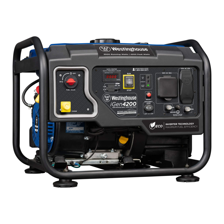
FEATURES
IGEN4200 FEATURES

- Open frame inverter design: Quiet, fuel efficient power provided by a digital inverter built in a rugged open frame design.
- Choke lever: Pull to choke and push in to run once the engine has started.
- Oil Fill Plug/Dipstick: Must be removed to add and check oil.
- Muffler and Spark Arrestor: Avoid contact until the engine is cooled down. The spark arrestor prevents sparks from exiting the muffler. It must be removed for servicing.
- Recoil Handle: Pull to start the engine.
- Air-filter Access Cover: Gain access to air-filter for maintenance.
- Fuel Gauge: Indicates fuel level.
CONTROL PANEL FEATURES

- VFT Data Center: Press and release the mode button to toggle between Voltage, Frequency, Total Hour Meter and Run/Maintenance Timer.
![]()
The Run/Maintenance Timer displays the time in hours and minutes each time the generator is ran. The run timer resets to 00:00 when the generator is shut off. Built into this run timer is a maintenance reminder. When the new generator is ran for 25 hours, the meter will display P25. This is to remind you to change the oil after the initial 25 hours of run time. When it displays P50, it is time to clean the air filter. When it displays P100 it is time change/clean the fuel filter, clean the air filter, and change the oil. - Engine Control Switch: Switch to "Stop" to stop the engine. Switch to "Run" before starting engine.
- Indicator Lights:
Low Oil LED: Indicates low oil level.
Overload LED: Indicates that the inverter is overloaded.
Output Ready LED: Indicates the inverter is ready to be used. - Reset Breaker: If the inverter is overloaded, the reset breaker will trip. The engine will continue to run, but there will be no electrical power output from the inverter. Unplug the devices and reduce the load. Push in the reset breaker to reset it.
- 120-Volt 30 Amp TT-30 Outlet: Travel Trailer outlet can supply a maximum of 30 amps and 120 volts.
- 120-Volt, 20-Amp Duplex: The outlet is capable of carrying a maximum of 20 amps.
- USB Duplex: 5V DC USB outlets that come with 1 and 2.1 amp rating. 5-Volt DC USB devices or extension cords must be fitted with a standard Type "A" USB male plug for connection to the generator.
- Efficiency Mode Switch: Move the switch to the ON position when powering small resistive loads such as a computer or electric light; the engine speed will automatically be kept to a minimum, thereby reducing fuel consumption and noise. Select the OFF position when powering large inductive loads such as an air conditioner or electric pump; the engine speed will be kept higher for maximum electrical starting power.
- 30-Amp Circuit Breaker: Circuit breaker limits the current that can be delivered through the 120-volt TT-30R outlet to 30amps.
- Ground Terminal: The ground terminal is used to externally ground the inverter.
- 20-Amp Circuit Breaker: Circuit breaker limits the current that can be delivered through the 120-volt duplex outlets to 20amps.

OPERATION
BEFORE STARTING THE INVERTER

BEFORE STARTING THE INVERTER, REVIEW SAFETY SECTION.
Location Selection
Before starting the inverter, avoid exhaust and location hazards by verifying:
- You have selected a location to operate the inverter that is outdoors and well ventilated.
- You have selected a location with a level and solid surface on which to place the inverter.
- You have selected a location that is at least 15 feet (4.5 m) away from any building, other equipment or combustible material.
- If the inverter is located close to a building, make sure it is not located near any windows, doors and/ or vents.

| | |
 | Always operate the inverter on a level surface. Placing the inverter on non level surfaces can cause the inverter to tip over, causing fuel and oil to spill. Spilled fuel can ignite if it comes in contact with an ignition source such as a very hot surface. |
| NOTICE | |
Only operate the inverter on a solid, level surface. Operating the inverter on a surface with loose material such as sand or grass clippings can cause debris to be ingested by the inverter that could:
| |
Weather
Never operate your inverter outdoors during rain, snow or any combination of weather conditions that could lead to moisture collecting on, in or around the generator.
Dry Surface
Always operate the inverter on a dry surface free of any moisture.
No Connected Loads
Make sure the inverter has no connected loads before starting it. To ensure there are no connected loads, unplug any electrical extension cords that are plugged into the control panel receptacles.
| NOTICE | |
| Starting the inverter with loads already applied to it could result in damage to any appliance being powered off the inverter during the brief start-up period. |
Grounding the Generator
The National Electric Code (NEC), as well as many local electrical codes, may require the generator to be connected to earth ground. As the generator application has many variables that cannot be determined by the manufacturer of the generator, a licensed electrician will need to determine if a grounding rod is needed.
If a licensed electrician has determine the application requires a ground rod, make sure it is connected to earth ground by connecting the ground terminal on the control panel to earth ground using copper wire (minimum 10 AWG). Consult a qualified electrician for local grounding requirements.
Neutral Floating: The generator (stator winding) is isolated from the frame and from the AC receptacle ground pin.
Consult with your local municipalities for your grounding codes.
| | |
 | Be sure the inverter is properly connected to earth ground before operating. |
High Altitude Operation
Engine power is reduced the higher you operate above sea level. Output will be reduced approximately 3.5% for every 1000ft of increased altitude from sea level. This is a natural occurrence and cannot be adjusted by engine. Increased exhaust emissions can also result due to increased fuel mixture. Other issues include hard starting, increased fuel consumption and spark plug fouling. Contact our service team 1-855-944-3571 for altitude part kits.
High Altitude Carburetor Kit Part Number: 140546
POWERCORD
Using Extension Cords
Westinghouse Portable Power assumes no responsibility for the content within this table. The use of this table is the responsibility of the user only. This table is intended for reference only. The results produced by using this table are not guaranteed to be correct or applicable in all situations as the type and construction of cords are highly variable. Always check with local regulations and a licensed electrician prior to installing or connecting an electrical appliance.

POWER OUTPUT AND DEMAND
It is recommended that the generator should always be operated with at least one-third of its rated 120-Volt AC power output. 120-Volt AC devices have two different electric power demands that must be taken into consideration, namely the running power and the starting/peak power. Both are measured in Watts (typically abbreviated as "W").
The steady state continuous load is the running power demand and this is often marked on the device near its model number or serial number. Sometimes the device might only be marked with its voltage (i.e. 120 V) and current draw (e.g. 20 Amp or 20 A), in which case the running power demand in Watts can be obtained by multiplying the voltage times the current, e.g. 120V × 20 A = 2,400 W.
Simple resistive 120-Volt AC devices such as incandescent bulbs, toasters, heaters, etc. have no extra power demand when starting, and so their starting power demands are the same as their running power demands.
More complex 120-Volt AC devices containing inductive or capacitive elements such as electric motors have a momentary extra power demand when starting, which can be up to seven times the running power demand or more. Manufacturers of such devices rarely publish this starting power demand and so it's often necessary to estimate it. A rule of thumb for devices fitted with an electric motor is to apply a starting power multiplier of 1.2 for small hand-held or portable devices and a value of 3.5 for larger stationary devices. For example, a 900 W angle grinder can be assumed to have a starting power demand of at least 1.2 × 900 W, which equals 1,080 W. Similarly, a 1,650 W air compressor can be assumed to have a starting power demand of at least 3.5 × 1,650 W, which equals 5,775 W.
To prevent overloading of the generator's 120-Volt AC system:
- Add up the running power demand of all the 120-Volt AC devices that will be connected to the generator at one time. This total must not be greater than the generator's specified running power output.
- Add up the running power demand again, but for the largest motor-driven device use the value of its starting power demand instead of its running power demand. This total must not be greater than the generator's specified starting power output.
- The total running power demand of all the devices that will be connected to any one of the generator's outlets must not exceed the generator's specified running power output.
TRANSPORTING THE GENERATOR
The generator should be stopped and both the fuel control switch and fuel cap should be tight before transporting the generator. Keep the unit level during transport to minimize the possibility of fuel leakage or, if possible, drain out the fuel prior to transport.
If the generator has been operating, allow the unit to cool down before loading it onto the transport vehicle.
Use only the generator's fixed frame for lifting the unit or attaching any load restraints such as ropes or tie-down straps. Do not attempt to lift or secure the generator by holding onto any of its other components.
ADDING/CHECKING ENGINE FLUIDS AND FUEL
BEFORE ADDING/CHECKING ENGINE FLUIDS AND FUEL, REVIEW SAFETY SECTION.
| | |
 | Filling the fuel tank with gasoline while the inverter is running can cause gasoline to leak and come in contact with hot surfaces that can ignite the gasoline. |
Before starting the inverter, always check the level of:
- Engine oil
- Gasoline in the fuel tank
Once the inverter is started and the engine gets warm, it is not safe to add gasoline to the fuel tank or engine oil to the engine while the engine is running or the engine and muffler are hot.
CHECKING AND / OR ADDING ENGINE OIL
| | |
 | Internal pressure can build in the engine crankcase while the engine is running. Removing the oil fill plug/ dipstick while the engine is hot can cause extremely hot oil to spray out of the crankcase and can severely burn skin. Allow engine oil to cool for several minutes before removing the oil fill plug/dipstick. |
The unit as shipped does not contain oil in the engine. You must add engine oil before starting the inverter for the first time. See Checking Engine Oil and Adding Engine Oil for instructions on checking engine oil level and the procedure for adding engine oil.
| NOTICE |
| The engine does not contain engine oil as shipped. Attempting to start the engine without adding engine oil will permanently damage internal engine components. The engine is equipped with a low oil shutdown switch. If the oil level becomes low, the engine may shut down and not start until the oil is filled to the proper level. The owner of the inverter is responsible to ensure the proper oil level is maintained during the operation of the generator. Failure to maintain the proper oil level can result in engine damage. |
ADDING GASOLINE TO THE FUEL TANK
| | |
| | Never refuel the inverter while the engine is running. |
 | Always turn the engine off and allow the inverter to cool before refueling. |
| | |
 | Avoid prolonged skin contact with gasoline. Avoid prolonged breathing of gasoline vapors. |
Required Gasoline
Only use gasoline that meets the following requirements:
- Unleaded gasoline only
- Gasoline with maximum 10% ethanol added
- Gasoline with an 87 octane rating or higher
Filling the Fuel Tank
Follow the steps below to fill the fuel tank:
- Shut off the inverter.
- Allow the inverter to cool down so all surface areas of the muffler and engine are cool to the touch.
- Move the inverter to a flat surface.
- Clean area around the fuel cap.
- Remove the fuel cap by rotating counterclockwise.
NOTICE Do not overfill the fuel tank. Spilled fuel will damage some plastic parts. - Slowly add gasoline into the fuel tank. Be very careful not to overfill the tank. The gasoline level should NOT be higher than the red ring (see Figure 1).

Figure 1: Maximum gasoline fill level - Install the fuel cap by rotating clockwise.

STARTING THE INVERTER
BEFORE STARTING THE INVERTER, REVIEW SAFETY SECTION.
For proper starting and operation of the inverter, make sure you review the inverter control panel features and their descriptions.
Before attempting to start the inverter, verify the following:
- The engine is filled with engine oil (see Engine Oil Correct Level).
- The inverter is situated in a proper location (see Location Selection).
- The inverter is on a dry surface (see Weather and Dry Surface).
- All loads are disconnected from the inverter (see No Connected Loads).
- The inverter is properly grounded (see Grounding the Inverter)
| | |
 | Never use the inverter in a location that is wet or damp. Never expose the inverter to rain, snow, water spray or standing water while in use. Protect the inverter from all hazardous weather conditions. Moisture or ice can cause a short circuit or other malfunction in the electrical circuit. |
 | Never operate the inverter in an enclosed area. Engine exhaust contains carbon monoxide. Only operate the inverter outside and away from windows, doors and vents. |
Starting iGen4200
- Move inverter to a flat surface outside in a well ventilated area away from open doors or windows.
- Check oil levels. If it is the first time starting make sure to add oil (see Adding Engine Oil).
- Disconnect all electrical loads from the generator.
- Make sure the circuit breakers are properly set (see Figure 2 below).
![]()
Figure 2: Breaker position- 120V Breaker Operating Position
- 120V Breaker Tripped Position
- Turn the fuel valve switch to ON position (see Figure 3).
![]()
Figure 3: Fuel valve - ON - Push the engine control switch into the RUN position (see Figure 4).
![]()
Figure 4: Engine control switch - RUN - For cold starting, pull out the choke lever on the control panel (see Figure 5).

Figure 5: Pull choke lever - Firmly grasp and pull the recoil handle slowly until you feel increased resistance. At this point, apply a rapid pull while pulling up and slightly away from the generator.
- As the engine starts and stabilizes, push the choke lever in.
- Plug in devices.


STOPPING THE INVERTER
Normal Operation
During normal operation, use the following steps to stop your inverter:
- Remove any connected loads from the control panel receptacles.
- Allow the inverter to run at "no load" to reduce and stabilize engine and alternator temperatures.
- Push the engine control switch to the STOP position (see Figure 6).
![]()
Figure 6: Push engine control switch to STOP position

During an Emergency
If there is an emergency and the inverter must be stopped quickly, move the engine control switch to the STOP position immediately (see Figure 6).
USING EFFICIENCY MODE
The inverter is equipped with an efficiency mode switch to minimize fuel consumption. In efficiency mode, the inverter will sense the load and adjust the engine RPM to the current load requirements. Efficiency mode should be used only after the inverter has been warmed up to operating temperature.
- To turn on the efficiency mode, press the switch to the ON position).
- If no load is present, the inverter RPM will drop down to an idle speed.
- As a load is applied, the inverter will sense the load and engine RPM will increase according to the load applied.
- To run the inverter at maximum power and RPM, press the efficiency mode switch to the OFF position.
RESETTING THE RESET BREAKER
The inverter will trip the breaker and automatically disconnect from the load when the controls sense a predetermined overload condition. The inverter engine will continue to run, but there will not be any electrical output.
- Turn off all devices and unplug them from the inverter.
- Determine the wattage required from the devices being powered by the inverter (see Power Output and Demand). Make sure the wattage required does not exceed the maximum output of the inverter.
- Press in the reset breaker to reset it (see Figure 7).

Figure 7: Press in reset breaker - Plug the devices in to the inverter.
- Turn on the devices as needed.

MAINTENANCE
BEFORE PERFORMING MAINTENANCE ON THE INVERTER, REVIEW THE SAFETY SECTION, AS WELL AS THE FOLLOWING SAFETY MESSAGES.
| | |
 | Avoid accidentally starting the inverter during maintenance by removing the spark plug boot from the spark plug. For electric start inverters, also disconnect the battery cables from the battery (disconnect the black negative (-) cable first) and place the cables away from the battery posts to avoid arcing. |
| | Allow hot components to cool to the touch prior to performing any maintenance procedure. |
 | Internal pressure can build in the engine crankcase while the engine is running. Removing the oil fill plug/ dipstick while the engine is hot can cause extremely hot oil to spray out of the crankcase and can severely burn skin. Allow engine oil to cool for several minutes before removing the oil fill plug/dipstick. |
 | Always perform maintenance in a well-ventilated area. Gasoline fuel and fuel vapors are extremely flammable and can ignite under certain conditions. |
| | |
 | Avoid skin contact with engine oil or gasoline. Prolonged skin contact with engine oil or gasoline can be harmful. Frequent and prolonged contact with engine oil may cause skin cancer. Take protective measures and wear protective clothing and equipment. Wash all exposed skin with soap and water. |
| | |
 | Failure to perform periodic maintenance or not following maintenance procedures can cause the inverter to malfunction and could result in death or serious injury. |
| NOTICE | |
| Periodic maintenance intervals vary depending on inverter operating conditions. Operating the inverter under severe conditions, such as sustained high-load, high-temperature, or unusually wet or dusty environments, will require more frequent periodic maintenance. The intervals listed in the maintenance schedule should be treated only as a general guideline. | |
Following the maintenance schedule is important to keep the inverter in good operating condition. The following is a summary of maintenance items by periodic maintenance intervals.
TABLE 1: MAINTENANCE SCHEDULE - OWNER PERFORMED
| Maintenance Item | Before Every Use | After First 20 Hours or First Month of Use | After 50 Hours of Use or Every 6 Months | After 100 Hour of Use or Every 6 Months | After 300 Hours of Use or Every Year |
| Engine Oil | Check Level | Change | Change | - | - |
| Cooling Features | Check/Clean | - | - | - | - |
| Air Filter | Check | - | Clean* | - | Replace |
| Spark Plug | - | - | - | Check/Clean | Replace |
| Spark Arrestor | - | - | - | Check/Clean | - |
| Valve Clearance** | - | - | - | Check/Adjust | - |
*Service more frequently if operating in dry and dusty conditions
**Recommend to have service done by authorized Westinghouse service dealer
ENGINE OIL MAINTENANCE
Engine Oil Specification
- Only use the engine oil specified in Figure 8.

Figure 8: Recommended oil - Only use 4-stroke/cycle engine oil. NEVER USE 2-STROKE/CYCLE OIL. Synthetic oil is an acceptable substitute for conventional oil.

CHECKING ENGINE OIL
| NOTICE |
| Always maintain proper engine oil level. Failure to maintain proper engine oil level could result in severe damage to the engine and/or shorten the life of the engine. Always use the specified engine oil. Failure to use the specified engine oil can cause accelerated wear and/ or shorten the life of the engine. |
Engine oil level should be checked before every use.
- Always operate or maintain the inverter on a flat surface.
- Stop engine if running.
- Let engine sit and cool for several minutes (allow crankcase pressure to equalize).
- With a damp rag, clean around the oil fill plug.
- Remove the oil fill plug/dipstick (see Figure 9).
![]()
Figure 9: Oil fill plug/dipstick location - Check oil level: When checking the engine oil, remove the oil fill plug/dipstick and wipe it clean. Thread the oil fill plug/dipstick all the way back in and then remove and check the oil level on the oil fill plug/dipstick.
- Acceptable Oil Level – Oil is visible on the crosshatches between the H and L lines on the oil fill plug/dipstick (see Figure 10).

Figure 10: Oil level - Low Oil – Oil is below the L line on the oil fill plug/ dipstick.
- Acceptable Oil Level – Oil is visible on the crosshatches between the H and L lines on the oil fill plug/dipstick (see Figure 10).


| NOTICE |
| Engine oil must always be checked and added when the inverter is on a flat, level surface, or an inaccurate reading may result, causing serious engine damage. |
ADDING ENGINE OIL
- Always operate or maintain the inverter on a flat surface.
- Stop engine if running.
- Let engine sit and cool for several minutes (allow crankcase pressure to equalize).
- Thoroughly clean around the oil fill plug/dipstick.
- Remove the oil fill plug/dipstick (see Figure 9).
- Select the proper engine oil as specified in Figure 8.
- Using the supplied oil funnel, slowly add engine oil to the engine. Stop frequently to check the oil level and avoid overfilling.
- Continue to add oil until the oil is at the correct level then replace oil fill plug/dipstick.
CHANGING ENGINE OIL
- Always operate or maintain the generator on a flat surface.
- Stop the engine.
- Let engine sit and cool for several minutes (allow crankcase pressure to equalize).
- Place oil pan (or suitable container) under the oil drain bolt (see Figure 11).
![]()
Figure 11: Remove oil drain bolt - With a damp rag, thoroughly clean around the oil drain bolt.
- Remove the oil drain bolt (see Figure 11). Once removed, place the oil drain bolt on a clean surface.
- Allow oil to completely drain.
- Replace oil drain bolt.
- Dispose of used engine oil properly.
- Fill crankcase with oil following the steps outlined in Adding Engine Oil.

| NOTICE |
| Never dispose of used engine oil by dumping the oil into a sewer, on the ground, or into groundwater or waterways. Always be environmentally responsible. Follow the guidelines of the EPA or other governmental agencies for proper disposal of hazardous materials. Consult local authorities or reclamation facility. |
AIR FILTER MAINTENANCE
| | |
 | Never use gasoline or other flammable solvents to clean the air filter. Use only household detergent soap to clean the air filter. |
Cleaning the Air Filter
The air filter must be cleaned after every 50 hours of use or 3 months (frequency should be increased if inverter is operated in a dusty environment).
- Turn off the inverter and let it cool for several minutes if running.
- Unscrew the two bolts on air filter cover and set aside (see Figure 12).
![]()
Figure 12: Remove air filter - Remove the foam element from the air cleaner housing.
- Wash the foam air filter element by submerging the element in a solution of household detergent soap and warm water. Slowly squeeze the foam to thoroughly clean.
NOTICE NEVER twist or tear the foam air filter element during cleaning or drying. Only apply slow but firm squeezing action. - Rinse in clean water by submerging the air filter element in fresh water and applying a slow squeezing action (see Figure 13).
![]()
Figure 13NOTICE Never dispose of soap cleaning solution used to clean the air filter by dumping the solution into a sewer, on the ground, or into ground water or waterways. Always be environmentally responsible. Follow the guidelines of the EPA or other governmental agencies for proper disposal of hazardous materials. Consult local authorities or reclamation facility. - Dispose of used soap cleaning solution properly.
- Dry the air filter elements by again applying a slow firm squeezing action.
- Once the air filters are dry, coat the air filters with clean engine oil (see Figure 14 below).
![]()
Figure 14 - Squeeze the filters to remove any excess oil.
- Install the filters back into the unit.
- Install the air filter cover and secure the bolts you removed.


DRAINING THE FLOAT BOWL
- Locate carburetor float bowl above air filter (see Figure 15).
![]()
Figure 15: Carburetor float bowl - Locate the clear plastic hose from the float that is exiting out the bottom of the inverter, and place a suitable container under it to catch the drained fuel (see Figure 16).

Figure 16: Fuel drain hose - Loosen the float bowl drain screw (see Figure 17) until fuel is seen draining from the float bowl.

Figure 17: Loosen float bowl screw - Allow fuel to drain into the container, and then tighten the float bowl drain screw.


| NOTICE |
| Never dispose of fuel by dumping fuel into a sewer, on the ground, or into groundwater or waterways. Always be environmentally responsible. Follow the guidelines of the EPA or other governmental agencies for proper disposal of hazardous materials. Consult local authorities or reclamation facility. |
SPARK PLUG MAINTENANCE
The spark plug must be checked and cleaned after every 100 hours of use or 6 months and must be replaced after 300 hours of use or every year.
- Stop the inverter and let it cool for several minutes if running.
- Remove the spark plug boot by firmly pulling the plastic spark plug boot handle directly away from the engine (see Figure 18).
![]()
Figure 18 - Remove spark plug bootNOTICE Never apply any side load or move the spark plug laterally when removing the spark plug. Applying a side load or moving the spark plug laterally may crack and damage the spark plug boot. - Clean area around the spark plug.
- Using the spark plug socket wrench provided, remove the spark plug from the cylinder head.
- Place a clean rag over the opening created by the removal of the spark plug to make sure no dirt can get into the combustion chamber.
- Inspect the spark plug for:
- Cracked or chipped insulator
- Excessive wear
- Spark plug gap (the acceptable limit of 0.027–0.032 in. [0.70 – 0.80 mm]).
![]()
- If the spark plug fails any one of the conditions listed above, replace the plug.
NOTICE Only use the recommended spark plug. Using a non-recommended spark plug could result in damage to the engine. - Install the spark plug by carefully following the steps outlined below:
- Carefully insert the spark plug back into the cylinder head. Hand-thread the spark plug until it bottoms out.
- Using the spark plug socket wrench provided, turn the spark plug to ensure it is fully seated.
- Replace the spark plug boot, making sure the boot fully engages the spark plug's tip.


Recommended Spark Plug Replacement:
NGK: BPR7ES (Replacement)
Torch: F7RTC (OE Spark Plug)
Westinghouse Part Number: 180526
CLEANING THE SPARK ARRESTOR
Check and clean the spark arrestor after every 100 hours of use or 6 months.
- Stop the inverter and let it cool for several minutes if running.
- Move the inverter to a flat, level surface.
- Remove the screws holding the inverter cover as well as the bolts and screw holding the inverter cover (see Figure 19).

Figure 19: Remove screws holding inverter and muffler cover - Once the inverter cover is removed, tilt the top of the muffler cover downward and pull out to remove it.
- Loosen the clamp holding the spark arrestor onto the muffler with a screw driver (see Figure 20).
![]()
Figure 20: Remove spark arrestor - Slide the spark arrestor band clamp off the spark arrestor screen.
- Pull the spark arrestor screen off the muffler exhaust pipe.
- Using a wire brush, remove any dirt and debris that may have collected on the spark arrestor screen.
- If the spark arrestor screen shows signs of wear (rips, tears or large openings in the screen), replace the spark arrestor screen.
- Install the spark arrestor components in the following order:
- Place spark arrestor screen over the muffler exhaust pipe. Push on the screen until it fully bottoms out.
- Place the spark arrestor band clamp over the screen and tighten with a screwdriver
- Replace the muffler cover and the inverter cover that you removed in step 4.


CHECKING AND ADJUSTING VALVE LASH
| | |
 | Checking and adjusting valve lash must be done when the engine is cold. |
- Remove the rocker arm cover and carefully remove the gasket. If the gasket is torn or damaged, it must be replaced.
- Remove the spark plug so the engine can be rotated more easily.
- Rotate the engine to top dead center (TDC) of the compression stroke. Looking through the spark plug hole, the piston should be at the top.
- Both the rocker arms should be loose at TDC on the compression stroke. If they are not, rotate the engine 360°.
- Insert a feeler gauge between the rocker arm and the push rod and check for clearance (see Figure 21). See table below for valve lash specifications.
![]()
Figure 21- Push Rod,
- Feeler Gauge Area
- Rocker Arm,
- Jam Nut,
- Adjusting Nut

Standard Valve Lash
| Intake Valve | Exhaust Valve | |
| Valve Lash | 0.0035 ± 0.0043 in (0.09 ± 0.11 mm) | 0.0043 ± 0.0051 in (0.11 ± 0.13 mm) |
| Bolt Torque | 8-12N.m | 8-12N.m |
- If an adjustment is required, hold the adjusting nut and loosen the jam nut.
- Turn the adjusting nut to obtain the correct valve lash. When the valve lash is correct, hold the adjusting nut and tighten the jam nut to 106 in-lb (12 N•m).
- Recheck the valve lash after tightening the jam nut.
- Perform this procedure for both the intake and exhaust valves.
- Install the rocker arm cover, gasket and spark plug.
CLEANING THE INVERTER
It is important to inspect and clean the inverter before every use.
Clean All Engine Air Inlet and Outlet Ports – Make sure all engine air inlet and outlet ports are clean of any dirt and debris to ensure the engine does not run hot.
STORAGE
| | ||
 | Never store an inverter with fuel in the tank indoors or in a poorly ventilated area where the fumes can come in contact with an ignition source such as a:
| |
| NOTICE | ||
| Gasoline stored for as little as 60 days can go bad, causing gum, varnish and corrosive buildup in fuel lines, fuel passages and the engine. This corrosive buildup restricts the flow of fuel, preventing an engine from starting after a prolonged storage period. | ||
Proper care should be taken to prepare the inverter for any storage
- Clean the inverter as outlined in Cleaning the Inverter.
- Siphon all gasoline from the fuel tank as best as possible.
- Start the engine and allow the inverter to run until all the remaining gasoline in the fuel lines and carburetor is consumed and the engine shuts off.
- Drain any remaining fuel from the float bowl. See Draining the Float Bowl.
- Change the oil (see Changing Engine Oil).
- Remove the spark plug (see Spark Plug Maintenance) and place about 1 tablespoon of oil in the spark plug opening. While placing a clean rag over the spark plug opening, slowly pull the recoil handle to allow the engine to turn over several times. This will distribute the oil and protect the cylinder wall from corroding during storage.
- Replace the spark plug (see Spark Plug Maintenance).
- Move the inverter to a clean, dry place for storage.

MAINTENANCE REMINDERS
The VFT meter on this unit has programmed maintenance reminders. When the VFT meter shows:

P25: This is to remind you to change the oil after the initial 25 hours of run time.

P50: It is time to clean the air filter.

P100: It is time change/clean the fuel filter, clean the air filter, and change the oil.
TROUBLESHOOTING
| | ||
 | Before attempting to service or troubleshoot the generator, the owner or service technician must first read the owner's manual and understand and follow all safety instructions. Failure to follow all instructions may result in conditions that can lead to voiding of the EPA certification or product warranty, serious personal injury, property damage or even death. | |
| PROBLEM | POTENTIAL CAUSE | SOLUTION |
| Engine is running, but no electrical output. |
|
|
|
| |
|
| |
|
| |
|
| |
| Engine will not start or remain running while trying to start. |
|
|
|
| |
|
| |
|
| |
|
| |
|
| |
|
| |
|
| |
|
| |
|
| |
| Inverter suddenly stops running. |
|
|
|
| |
|
| |
| Engine runs erratic; does not hold a steady RPM. |
|
|
|
| |
|
| |
| The VFT meter is showing "P" | The meter shows "P25" | Change oil |
| The meter shows "P50" | Clean air filter | |
| The meter shows "P100" | Change/clean the fuel filter, clean the air filter, and change the oil | |
iGen4200 SCHEMATIC

iGen4200 EXPLODED VIEW

iGen4200 EXPLODED VIEW PART NO.

iGen4200 ENGINE VIEW

iGen4200 ENGINE VIEW PART NO.

Service Hotline: (855) 944-3571
777 Manor Park Drive
Columbus, OH 43228
Documents / Resources
References

Download manual
Here you can download full pdf version of manual, it may contain additional safety instructions, warranty information, FCC rules, etc.
Advertisement


Need help?
Do you have a question about the iGen4200 and is the answer not in the manual?
Questions and answers