Table of Contents
Advertisement
Quick Links
Service Manual
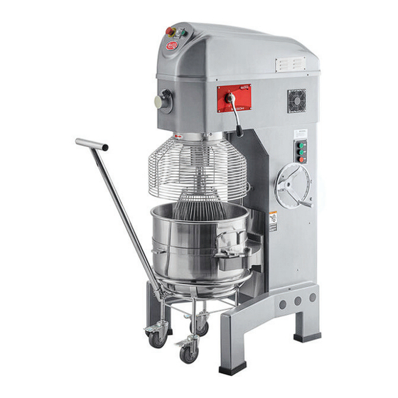
Planetary Floor Mixers
Models: 177MX30H, 177MX40H, 177MX60H
5/2023
NOTICE: This manual is for a certified service technician and should not be used by those who are not properly trained.
This manual cannot cover all possible conditions that may occur and is not intended to be all encompassing.
You should read this manual in its entirety and the specific repair you wish to do prior to starting the repair.
This will allow you to determine if you have the correct tools, instruments, and skills to perform the procedure.
www.AvantcoEquipment.com
1
Advertisement
Table of Contents

Related Manuals for Avantco 177MX30H


Summary of Contents for Avantco 177MX30H
- Page 1 Service Manual Planetary Floor Mixers Models: 177MX30H, 177MX40H, 177MX60H 5/2023 NOTICE: This manual is for a certified service technician and should not be used by those who are not properly trained. This manual cannot cover all possible conditions that may occur and is not intended to be all encompassing.
-
Page 2: Table Of Contents
177MX60H ............ 18 Lift Motor Button-'Drop' ........4 Lift Motor Button-'Stop' ........5 Parts Diagram ..........19 Timer ...............5 177MX30H Main .......... 19 Emergency Stop Button (E-Stop) ....6 177MX30 Electrical ........20 Start Button ............6 177MX30 Speed Assembly ......21 Lift Motor ............7 177MX30 Lift Handle Assembly ....22... -
Page 3: Troubleshooting
Check bowl slide is not jammed or loose Bowl does not go up or down Check lift arm mounting bolts (177MX30H & 177MX40H) Check lift arm hex nuts are tight and adjusted correctly Check lift arm assembly is operating correctly... -
Page 4: Parts Testing
Service Manual Part testing Fig. 1 LIFT MOTOR BUTTON - 'RISE' (Fig. 1 & 2) 1. Check for continuity. Ensure unit is turned 'OFF' and disconnected from the power supply. Disconnect the wire connections and note their locations. • Continuity should be found between 1 & 2 without depressing the button. -
Page 5: Lift Motor Button-'Stop
Service Manual Part testing Fig. 4 LIFT MOTOR BUTTON - 'STOP' (Fig. 4) 1. Check for continuity. Ensure unit is turned 'OFF' and disconnected from the power supply. Disconnect the wire connections and note their locations. • Continuity should NOT be found between 1 & 2 without depressing the button. -
Page 6: Emergency Stop Button (E-Stop)
Service Manual Part testing Fig. 7 EMERGENCY STOP BUTTON (E-STOP) (Fig. 7 & 8) 1. Check for continuity. Ensure unit is turned 'OFF' and disconnected from the power supply. Disconnect the wire connections and note their locations. • Continuity should NOT be found between 1 &... -
Page 7: Lift Motor
Service Manual Part testing Fig. 11 LIFT MOTOR (Fig. 11 & 12) 1. Check for resistance. Ensure unit is turned 'OFF' and disconnected from the power supply. Disconnect the wire connections and note their locations. • Resistance should be 5.0 Ω +/-10% across the wire connections;... -
Page 8: Motor Contactors
Service Manual Part testing Fig. 15 - A; contactor for Fig. 15 'RISE' action of lift motor Fig. 15 - B; contactor for MOTOR CONTACTORS 'DROP' action of lift motor (Fig. 15) Fig. 15 - C; contactor for auger motor 1. -
Page 9: Part Replacement
Service Manual Part Replacement Fig. 18 Fig. 19 PRE-MAINTENANCE For contactors, overload protectors, lift motor 1. Disconnect from the power supply. (Fig. 18) 2. Remove the Phillips screws holding the rear panel in place. (Fig. 19) For auger motor, planetary gears, timer, E-Stop 1. -
Page 10: Timer
Service Manual Part Replacement Fig. 24 Fig. 25 TIMER 1. Follow pre-maintenance steps. 2. Remove the upper cover to gain access to the rear of the timer. 3. Remove the wire terminals from the timer. Note their locations for new install. (Fig. 25) 4. -
Page 11: Lift Motor
Service Manual Part Replacement Fig. 29 Fig. 30 LIFT MOTOR 1. Follow pre-maintenance steps. 2. Remove the Phillips screws holding the lift arm control buttons to the side of the unit and remove the button panel to gain access to the inside of the unit. (Fig. 29) 3. -
Page 12: Auger Motor
Service Manual Part Replacement Fig. 35 AUGER MOTOR 1. Follow pre-maintenance steps. 2. Remove the top cover to gain access to the motor. 3. Disconnect wire connectors from overload protector terminals, note their locations for new motor installation. 4. Loosen the 4 hex head nuts holding the auger motor belts tensioned with a 24mm socket or wrench. -
Page 13: Auger Gearbox
Service Manual Part Replacement Fig. 38 Fig. 39 AUGER GEARBOX Follow pre-maintenance steps. With the drive belts removed, you can remove the large pulley by removing the hex nut with a 27mm socket or wrench. Push the pulley of the shaft of the motor. -
Page 14: Auger Gearbox Continued
Service Manual Part Replacement Fig. 44 Continued from previous page. AUGER GEARBOX CONTINUED 11. Use the pusher screws to lift the gearbox lid. Use a 6mm hex key to turn the screws in a even pattern keeping the lid flat. (Fig. 44) Prying the lid completely free from the shafts will be necessary. -
Page 15: Auger Gearbox Continued
Service Manual Part Replacement Fig. 51 Fig. 52 Continued from previous page. AUGER GEARBOX CONTINUED 1. The internal hub gear and shaft can then be removed by tilting it and lifting up. (Fig. 51 & 52) 2. Remove remaining axle shafts by reinstalling lid over shafts and installing the nuts and bolts that hold the lid to the shafts. -
Page 16: Planetary Gear
Service Manual Part Replacement Fig. 55 BOWL GUARD 1. Follow pre-maintenance steps. 2. Lower and remove the mixing bowl. 3. Remove screw hole covers to access guard mounting screws. (Fig. 55) 4. Remove socket head cap screws holding bowl guard in place with a 5mm hex key. Rotate guard around to access all screws as needed. -
Page 17: Wiring Diagram
Service Manual Wiring Diagram 177MX30H, 177MX40H K1 Overload protection switch 1C, 2C AC contact device K2 Bowl lift switch K3 Safety protect swtich K4 Urgency stop switch K5 Switch K Reactor K0 Fluctuate safety switch KT Time relay CA/CB Capacitor M Motor www.AvantcoEquipment.com... -
Page 18: 177Mx60H
Service Manual Wiring Diagram 177MX60H FR1 => Overload protector; Main motor, auger K4 => Emergency stop switch FR2 => Overload protector; Lift motor K5, SB2 & SB3 => Start switch 1C => Lift motor rise contactor K8 => Bowl Drop switch 2C =>... -
Page 19: Parts Diagram
Service Manual Parts Diagram 177MX30H MAIN ITEM NO. DESCRIPTION PART ITEM NO. DESCRIPTION PART Gear axle assembly Screw - bearing covers Initiative gear assembly Pulley - motor 177PMX40SRW Bowl guard Key stock - motor pulley 6mm x 30mm Speed assembly... -
Page 20: 177Mx30 Electrical
Service Manual Parts Diagram 177MX30H ELECTRICAL ITEM NO. DESCRIPTION PART ITEM NO. DESCRIPTION PART Power switch 177MXONOFF Bowl pin spring 177PMX40SPNG Screw - power cover M4 x 18mm Air vent cover 177PMX30GRDB Timer 177PMX Screw - air vent cover M6 x 8mm... -
Page 21: 177Mx30 Speed Assembly
Service Manual Parts Diagram ITEM NO. DESCRIPTION PART Hex nut - fork axle 177MX30H SPEED ASSEMBLY Fork axle 177PMX30FAX Fork nut M18 x 1.5m Fork spring Fork 177PMX Speed spring Speed O-ring 15mm x 2.65mm Screw - speed mount M5 x 14mm... -
Page 22: 177Mx30 Lift Handle Assembly
Service Manual Parts Diagram 177MX30H LIFT HANDLE ASSEMBLY ITEM NO. DESCRIPTION PART Handle end 177PMX40BALL Handle 177PMX30HNDL Key stock 6mm x 12mm Screw - lift mount M10 x 90mm Lift arm 177PMX30PULL Screw - lift block M6 x 30mm Screw - lift connection... -
Page 23: 177Mx30 Bowl Guard Assembly
Service Manual Parts Diagram 177MX30H BOWL GUARD ASSEMBLY ITEM NO. DESCRIPTION PART ITEM NO. DESCRIPTION PART Inner planet gear 177PMX34IGR Gear - small Screw - inner gear M6 x 30mm Bearing - upper 177PMX30TPL Guard - movable 177PMX30FGRD Bearing - lower... -
Page 24: Parts Diagram
Service Manual Parts Diagram 177MX40H MAIN ITEM NO. DESCRIPTION PART ITEM NO. DESCRIPTION PART Center axle assembly 177PMX40CAX Screw - lid mount M8 x 30mm Initiative axle assembly 177PMX40IAX Lid cover Gearing axle assembly 177PMX40 Key stock 5mm x 30mm Top cover 177PMX40COVR Motor... -
Page 25: 177Mx40H Electrical
Service Manual Parts Diagram 177MX40H ELECTRICAL ITEM NO. DESCRIPTION PART ITEM NO. DESCRIPTION PART Timer Overload protector Power switch 177PMX40OFF Electrical box 177PMX34ECVR Screw - panel mount M4 x 18mm AC contactor 177PMX60ACCP Air vent plate 177PMX30GRDB Screw - electric box mount M5 x 10mm Screw - air vent M6 x 8mm... -
Page 26: 177Mx40H Speed Assembly
Service Manual Parts Diagram 177MX40H SPEED ASSEMBLY ITEM NO. DESCRIPTION PART ITEM NO. DESCRIPTION PART Top hex nut Screw - speed mount M5 x 14mm Fork axle 177PMX40FAX Screw - handle mount M6 x 20mm Fork body Handle end 177PMX40BALL Fork nut M18 x 1.5mm Fork assembly... -
Page 27: 177Mx40H Lift Handle Assembly
Service Manual Parts Diagram 177MX40H LIFT HANDLE ASSEMBLY ITEM NO. DESCRIPTION PART ITEM NO. DESCRIPTION PART Handle end 177PMX40BALL Screw - lift block M6 x 30mm Handle 177PMX40HNDL Screw - lift connection M12 x 40mm Key stock 6mm x 14mm Hex nut Screw - lift mount M10 x 90mm... -
Page 28: 177Mx40H Bowl Guard Assembly
Service Manual Parts Diagram 177MX40H BOWL GUARD ASSEMBLY ITEM NO. DESCRIPTION PART ITEM NO. DESCRIPTION PART Gear ring 177PMX34IGR Turning plate 177PMX40TPL Screw - gear ring mount M6 x 30mm Bearing - lower 6006 Screw rubber cap Handle end 177PMX40SEAL Guard - movable 177PMX40RGRD Key stock... -
Page 29: 177Mx60H Top Parts Assembly
Service Manual Parts Diagram 177MX60H TOP PARTS ASSEMBLY ITEM NO. DESCRIPTION PART ITEM NO. DESCRIPTION PART Top cover Screw - handle mount M10 x 90mm Emergency stop 177PMX60OFF Caster - cart 177PMX60CAST Timer Cart assembly 177PMX60CART Start switch 177PMX60ON www.AvantcoEquipment.com... -
Page 30: 177Mx60H Electrical Assembly
Service Manual Parts Diagram 177MX60H ELECTRICAL ASSEMBLY ITEM NO. DESCRIPTION PART ITEM NO. DESCRIPTION PART Front hub cover Thermo protector(5A) 177PMX605 Bowl installed rod Thermo protector(16A) 177PMX606 Screw - cover mount M6 x 8mm AC contactor lift motor 177PMX60ACCP Screw - switch cover M5 x 8mm AC contactor auger motor 177PMX60AC18... -
Page 31: Parts Diagram
Service Manual Parts Diagram 177MX60H GEARBOX ITEM NO. DESCRIPTION PART ITEM NO. DESCRIPTION PART Gear axle assembly 177PMX60GAX Speed handle assembly Center axle assembly Grease plug Initiative axle assembly 177PMX60IAX Screw - bearing cover M5 x 8mm Fork assembly 177PMX60FORK www.AvantcoEquipment.com... -
Page 32: 177Mx60H Motor
Service Manual Parts Diagram 177MX60H MOTOR ITEM NO. DESCRIPTION PART Belt Screw - pulley mount M8 x 20mm Pulley - motor Screw - motor mount M14 x 30mm cap Motor Key stock M8 x 35mm Hex nut - mount plate www.AvantcoEquipment.com... -
Page 33: 177Mx60H Speed Assembly
Service Manual Parts Diagram 177MX60H SPEED ASSEMBLY ITEM NO. DESCRIPTION PART ITEM NO. DESCRIPTION PART Hex nut Screw - handle mount M6 x 20mm Fork axle 177PMX60FAX Speed handle Fork body Handle end Speed O-ring 24x18x3 Fork assembly 177PMX60FORK Screw - speed mount M6 x 16mm Speed handle assembly www.AvantcoEquipment.com... -
Page 34: 177Mx60H Guard Assembly
Service Manual Parts Diagram 177MX60H GUARD ASSEMBLY ITEM NO. DESCRIPTION PART ITEM NO. DESCRIPTION PART Guard - movable Guard - fixed Screw cover rubber Screw - upper axle M10 x 20mm Guard safety switch 177PMX30SW Small gear Screw - safety mount M5 x 8mm Bearing - mixing axle 6207... -
Page 35: 177Mx60H Lift Assembly
Service Manual Parts Diagram 177MX60H LIFT ASSEMBLY ITEM NO. DESCRIPTION PART ITEM NO. DESCRIPTION PART Screw - lift pulley M6 x 16mm Large pulley - lift Small pulley - lift 177PMX60BLWL Button - rise 177PMX60FLUC Key stock 6mm x 28mm Button - drop 177PMX60FLUC Lift motor...
Need help?
Do you have a question about the 177MX30H and is the answer not in the manual?
Questions and answers