Advertisement
Quick Links
41.21 · Technische Änderungen vorbehalten · Technical amendments reserved · Modifications techniques réservées
!
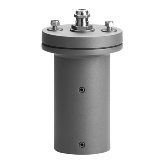
Aufsatzmuffe
Pole cap
Manchon
Gebrauchsanweisung
Anwendung
Aufsatzmuffe für die Montage eines
Hochleistungsscheinwerfers auf einen
Lichtmast.
Produktbeschreibung
Aufsatzmuffe besteht aus Aluminiumguss und
Edelstahl
Für Mastzopf ø 60 mm
Einstecktiefe 150 mm
Scheinwerferbefestigung auf einem drehbaren
Klemmteller mit zwei M8-Schrauben,
Abstand 80 mm und G½ Gewindestutzen mit
U-Scheibe und Mutter
1 Leitungsverschraubung für Scheinwerfer-
anschlussleitung von ø 8–11 mm
Schutzklasse I
c – Konformitätszeichen
Gewicht: 1,7 kg
Sicherheit
Für die Installation und für den Betrieb
dieses Ergänzungsteils sind die nationalen
Sicherheitsvorschriften zu beachten.
Die Montage und Inbetriebnahme darf nur
durch eine Elektrofachkraft erfolgen.
Der Hersteller übernimmt keine Haftung für
Schäden, die durch unsachgemäßen Einsatz
oder Montage entstehen.
Werden nachträglich Änderungen an dem
Ergänzungsteil vorgenommen, so gilt derjenige
als Hersteller, der diese Änderungen vornimmt.
Montage
Leitungsverschraubung und G½ Mutter mit
U-Scheibe und Zahnscheibe demontieren.
Klemmteller abnehmen und unter den
Scheinwerferbügel montieren.
Schraubenverbindung 2 x M8 fest anziehen.
Anzugsdrehmoment = 12 Nm
Scheinwerfer mit Klemmteller über den
G½ Gewindestutzen führen und mit U-Scheibe
und G½ Mutter befestigen.
Anzugsdrehmoment = 80 Nm
Leitungsverschraubung montieren und
Scheinwerferanschluss vornehmen.
Leitungsverschraubung dicht verschrauben.
Leitung in den Mastzopf einführen.
Aufsatzmuffe mit Scheinwerfer auf Mastzopf
setzen, ausrichten und mit seitlichen
Schrauben M8 festsetzen.
Anzugsdrehmoment = 12 Nm.
Ø 120
Ø 120
80
80
Ø 60
Ø 60
Instructions for use
Application
Pole cap for installation of one a high-
performance floodlight on a pole.
Product description
Pole cap made of aluminium alloy and stainless
steel
For pole top ø 60 mm
Slip fitter insert depth 150 mm
Fixing of floodlight on a rotatable clamping plate
with 2 screws M8, 80 mm spacing and G½
threaded connector end with washer and nut
1 screw cable gland for floodlight connecting
cable from ø 8–11 mm
Safety class I
c – Conformity mark
Weight: 1.7 kg
Safety
The installation and operation of this accessory
are subject to national safety regulations.
Installation and commissioning may only be
carried out by a qualified electrician.
The manufacturer accepts no liability for
damage caused by improper use or installation.
If modifications are subsequently made
to the accessory, the person who makes
these modifications shall be considered the
manufacturer.
Installation
Disassemble screw cable gland and G½ nut
with washer and lock washer.
Remove clamping plate and fix under floodlight
bracket.
Tighten screw connection 2 x M8 firmly.
Torque = 12 Nm
Place floodlight with clamping plate over the
G½ threaded connector end and fix with
washer and G½ nut.
Torque = 80 Nm
Assemble screw cable gland and connect
floodlight.
Tighten screw cable glands firmly.
Lead mains supply cable into pole top.
Place pole top cap with floodlight on pole top,
align and fix with lateral fixing screw M8.
Torque = 12 Nm.
BEGA Gantenbrink-Leuchten KG · Postfach 31 60 · 58689 Menden · info @ bega.com · www.bega.com
Fiche d'utilisation
Utilisation
Manchon pour l'installation d'un projecteur ultra
puissant sur un mât.
Description du produit
Manchon fabriquée en fonderie d'alu et acier
inoxydable
Pour tête de mât ø 60 mm
Profondeur d'embout 150 mm
Fixation du projecteur sur un disque de serrage
avec 2 vis M8, entraxe 80 mm et raccord fileté
G½ avec écrou et presse-étoupe
1 presse-étoupe pour câble de projecteur
de ø 8–11 mm
Classe de protection I
c – Sigle de conformité
Poids: 1,7 kg
Sécurité
Pour l'installation et l'utilisation de cet
accessoire, respecter les normes de sécurité
nationales.
L'installation et la mise en service ne doivent
être effectuées que par un électricien agréé.
Le fabricant décline toute responsabilité pour
tout dommage résultant d'une mise en œuvre
ou d'une installation inappropriée du produit.
Si des modifications sont ultérieurement
apportées à cet accessoire, l'intervenant qui les
effectuera sera considéré comme fabricant.
Installation
Démonter le presse-étoupe et l'écrou G½ avec
la rondelle et la rondelle éventail.
Retirer le disque de serrage et installer le sous
l'étrier du projecteur.
Serrer fermement le vissage 2 x M 8.
Moment de serrage = 12 Nm.
Guider le projecteur avec le disque de serrage
sur le raccord fileté G1/2 et fixer avec la
rondelle et l'écrou G½.
Moment de serrage = 80 Nm.
Installer le presse-étoupe et procéder au
raccordement électrique du projecteur.
Visser de facon étanche les presse-étoupes.
Introduire le câble de raccordement dans
l'ouverture au sommet du mât.
Placer le manchon avec le projecteur sur le
mât, ajuster et fixer avec les vis latérales M8.
Moment de serrage = 12 Nm.
70 341
1 / 2
Advertisement

Related Manuals for BEGA 70 341


Summary of Contents for BEGA 70 341
- Page 1 Torque = 12 Nm. mât, ajuster et fixer avec les vis latérales M8. Anzugsdrehmoment = 12 Nm. Moment de serrage = 12 Nm. BEGA Gantenbrink-Leuchten KG · Postfach 31 60 · 58689 Menden · info @ bega.com · www.bega.com 1 / 2...
- Page 2 Coppia di serraggio = 12 Nm. M8 aan de zijkant vast. Par de apriete = 12 Nm. Aanhaalmoment = 12 Nm. 2 / 2 BEGA Gantenbrink-Leuchten KG · Postfach 31 60 · 58689 Menden · info @ bega.com · www.bega.com...
Need help?
Do you have a question about the 70 341 and is the answer not in the manual?
Questions and answers