Table of Contents
Advertisement
Quick Links
Advertisement
Table of Contents

Subscribe to Our Youtube Channel
Related Manuals for STIEBEL ELTRON MSMW


Summary of Contents for STIEBEL ELTRON MSMW
- Page 1 MSMW, MSMS Mixer and swimmingpool module for heater system heat pumps Operating and installation instructions 11/02 Assembly as well as the initial start-up and maintenance of the device may be carried out by authorised skilled personnel only, in accordance with these instructions.
-
Page 2: Table Of Contents
Heating curve Positioning of temperature sensor 23 Heater program Circulation pump and mixer Swimming pool temperature BUS connection Swimming pool program MSMW connection field MSMS connection field Start-up BUS initialisation supplement 26 System configuration Reset capabilities Start-up list Explanations on... -
Page 3: General
Control of a second, independent mixer MSMS control cabinet model and the second circuit the MSMW in a wall-mounted housing. At the Control of an additional 4 buffer tank point of installation a bus line is laid between charging pumps... -
Page 4: Operating Instructions
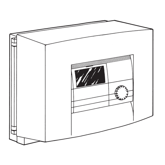
Operating instructions (For operator and skilled personnel) 1 Unit overview System status display A Display Mixer opens B Rotary control Mixer closes C Reset / Auto rotary control Circulation pump heater circuit 3 “Mixer circuit” D Programming key Circulation pump Swimmingpool Programming indicator lamp Buffer tank charging pump 3 Not assigned... - Page 5 Display (with all display elements) The meaning behind the display elements is dependent upon the control level: 1. Control level 2. Control level 3. Control level (Operating modes) (Start-up) Weekday Weekday – Time time, Code, parameter, Temperatures, temperature, Party hours, time interval, Holiday period Software,...
-
Page 6: Control Process
2 Control sequence In brief All settings are made according to the same Operation is split up into 3 control levels. The scheme: 1st. and 2nd. control levels are necessary for both the user and the skilled technician. When the control panel is The 3rd. -
Page 7: Settings
3 Settings 3.1 Operating modes (1st. control level) The operating modes can be altered when the control panel is closed by pressing the -button. Explanation Description Application Standby mode Control is switched off, but not During the holiday period de-energised; only the frost protection is active. -
Page 8: Room Temperature
3.2 Room temperature (2nd. control level ... ) The room temperature 3 system parameter can be used to set the specific room temperature for the heater circuit 3’s day and lowering modes. If you decide that the temperature in your room is too cold or warm then you can alter the room temperature. -
Page 9: Weekday And Timer
3.3 Weekdays and timer The Weekday/timer system parameter enables you to set the weekday and the time. Note: If a BUS connection has been established to the WPM the weekday and time can automatically be synchronised using the WPM. If the MSM is used as an independent mixer control, then both the weekday and time have to be set on the MSM. -
Page 10: Holiday And Party Program
3.4 Holiday and party programme 3.4.1 Holiday programme In the holiday programme the mixer circuit regulates the lowering temperature and the swinningpool function is set to "OFF". The holiday period is entered in days. The start and end time for the holiday program is always 12 noon. If the holiday period is entered in the morning, the system will enter the holiday programme at 12 noon on that day. - Page 11 3.4.2 Party program By using the party program system parameter you can extend the mixer circuit’s daytime operating mode by several hours. At the end of the specified time (hours) the heat-pump system will resume operation according to the heater program. This display will be shown only if the mixer flow sensor is connected.
-
Page 12: Temperature Information
3.5 Temperature information The Temperature information system parameter enables you to read off the sensor temperatures of the heat pump or the heat-pump system in a target and actual value comparison and the heating curve interval. All in all, 5 parameters can be requested (see table). This display will be shown only if the mixer flow sensor is connected. -
Page 13: Heating Curve
3.6 Heating curve The heating curve system parameter can be used to set a heating curve for the mixer circuit (H3). Only if the correct heating curve is used for each particular building will the room temperature remain constant for every outside temperature. The correct choice of heating curve is therefore of particular significance! Note: Your skilled service technician has set a building and configuration-related ideal heating curve for the mixer circuit. -
Page 14: Heater Program
3.7 Heater program Using the heater program system parameter you can set the respective heater program H3 for heater circuit 3. It is possible to specify three switching time pairs (I, II, III) for each single day of the week or for the weekdays (Mon – Fri) and the weekend (Sat – Sun) or for the entire week. This enables you to determine when and how often the heat-pump system should provide heat during daytime and lowering mode operation. - Page 15 Press the -key (indicator lamp goes out) and the set value is stored. Start of lowering operation (End of daytime operation) Press the button until the starting time for the lowering operation (parameter 12) appears in the display. Parameter Lowering mode If you press the -key (indicator lamp goes on) you can then use the...
- Page 16 Now you can set the heater program for the Sat - Sun weekend. Turn the -button until the weekend days from Saturday to Sunday (6 7) appear in the display with the attendant parameters 09. Start daytime mode Press the -key and the display will then show, in addition to the weekdays, the starting time for the daytime operation with the parameters 11 and the switching time pair I.
-
Page 17: Swimming Pool Temperature
3.8 Swimming pool temperature You can set the required temperature for heating the swimming pool with the swimming pool temperature system parameter. As soon as the actual temperature is less than the required temperature minus start-up hysteresis and the swimming pool program is operating in enable mode, swimming pool preparation is initiated. -
Page 18: Swimming Pool Program
3.9 Swimming pool program You can set the swimming pool operating times with the swimming pool program system parameter. It is possible to define two pairs of switching times (I, II) for each individual day of the week, or else for weekdays (Mon – Fri) and the weekend (Sat – Sun), or for the entire week. In this way you determine when and how often the heat pump system is to generate heat for swimming pool operation. - Page 19 Start of swi. pool If you now press the –button, in addition to the weekdays, operation the start time for swimming pool preparation will appear in the display. If the -button is pressed again, the indicator above the button will be illuminated. Using the –knob, you can now change the required start time of daily operation for the first pair of switching times.
-
Page 20: Assembly Instructions
– Cable harness – Connector – 1 PTC sensors (clip-on / external sensor) – 18 strain reliefs 2 Wall assembly (MSMW) The MSM may only be installed in a dry room. The permissible ambient temperature lies between 0 and 50 °C. -
Page 21: Electrical Connection
– Sensor leads to be strain relieved in accordance with specifications (applies to MSMW only). Mains and extra-low voltage are to be de- signed such that they are integrated into the wall-installation housing. This isolation must be adhered to for the installation. -
Page 22: Temperature Sensor
In case of systems without buffer tank, the sensor has to be installed in the return of the Heat pump. Diameter: 6mm Length: X2. 9 X2. 10 MSMW X11. 1 X11. 2 X11. 3 MSMS... -
Page 23: Positioning Of Temperature Sensor
MSM indicator symbol jumps straight to the room temperature 3 system parameter. All settings can be made on the MSM. (see MSMW Operating instructions). The time and the weekday do not have to be set as both are taken over by the WPM. -
Page 24: Msmw Connection Field
All cables are routed into the guide channels and fastened to the wall installation housing using the strain reliefs (red wedge). The connections must be made in accordance with the legend on the MSMW. Extra-small voltage range... -
Page 25: Msms Connection Field
4.9 MSMS connection field The connection at the mixer module is to be conducted in accordance with the illustrated connection field. To this end the enclosed connectors are to be plugged in for final assignment to the MSM as follows: X11 1 Terminal 1 of FE 6 remote control X22 1... -
Page 26: Start-Up
If incorrectly initialised 5 Start-up all the IHCs and the MSM must be reset, i.e. initialised again. 5.1 BUS initialisation supplement This must be done as follows: (applies for Sections 4.5.1 and 4.5.2) – Switch off supply voltage to the WPM It is essential that the following sequence be –... -
Page 27: Reset Capabilities
5.3 MSM reset capabilities 5.3.1 Reset by turning the rotary control switch to Auto then Reset and back again. The system-specific programming is retained. 5.3.2 Reset by turning the rotary control switch Auto to Reset and back again whilst simultaneously pressing the PRG key. EEPR must appear in the display. (EEPROM hardware reset). -
Page 28: Start-Up List
5.5 Start-up list explanations When starting up the heat-pump system the system-specific parameters also have to be defined along with the configuration in the 2nd. control level. These are set in the 3rd. code protected control level. The parameters are to be checked successively. Set values should be entered in the start-up list’s designated column (system value). - Page 29 Mixer operating period To ensure that mixer regulation functions reliably and quickly, the mixer cycle time [sec.] has to be entered for the mixer. The default value must be maintained for Stiebel Eltron mixers. Relay test By turning the rotary switch this parameter enables all the relays in the MSM to be individu- ally controlled.
-
Page 30: Technical Data
5.6 Technical data MSMW MSMS Supply voltage 230 V +/-10 %, 50 Hz Power consumption Max. 8 VA Degree of protection as under EN 60529 IP 21 IP 20 Protective class as under EN 60730 Type 1B Software class A... -
Page 31: Table
5.8 Table You can enter your programmed individual values in this table. Heater circuit Switching time pair I Switching time pair II Switching time pair III Mon. Tue. Wed. Thur. Fri. Sat. Sun. Mon. - Fri. Sat. – Sun. Swimming pool program Switching time pair I Switching time pair II Mon. -
Page 32: Measures In Event Of Malfunctions
6 measures in event of malfunctions 6.1 Malfunction indicator on display: Sensor fault The fault code relates to the temperature sensor, which could be called up under the Temperature information system parameter. In the event of a malfunction the fault is shown on the display. - Page 33 1 Outside temperature sensor Swimmingpool 2 Actual room temperature sensor 4 Actual HP return line temperature 5 Actual warm water temperature sensor Heating- Heating- 6 Actual mixer flow temperature sensor HC 2 circuit 2 circuit 3 7 Actual mixer flow temperature sensor HC 3 8 Actual source flow temperature sensor 9 Actual swimming pool return line sensor Buffer charging pump 1...
-
Page 34: Systemschematics
7.0 Systemschematic 2... - Page 35 Notes...
- Page 36 Internet www.stiebel-eltron.com Polska Stiebel Eltron sp.z. o.o Belgique ul. Instalatorów 9 PL-02-237 Warszawa Stiebel Eltron Sprl / Pvba 022-8 46 48 20 Fax 022-8 46 67 03 Rue Mitoyenne 897 B-4840 Welkenraedt E-Mail stiebel@stiebel-eltron.com.pl 087-88 14 65 Fax 087-88 15 97 Internet www.stiebel-eltron.com.pl...
Need help?
Do you have a question about the MSMW and is the answer not in the manual?
Questions and answers