Table of Contents
Advertisement
Quick Links
Model
BLRTA045-3990-10S
Download the latest version of this document at
http://www.desouttertools.com/info/6159929740_EN
Read all safety warnings and instructions
Failure to follow the safety warnings and instructions may result in
electric shock, fire and/or serious injury.
Save all warnings and instructions for future reference
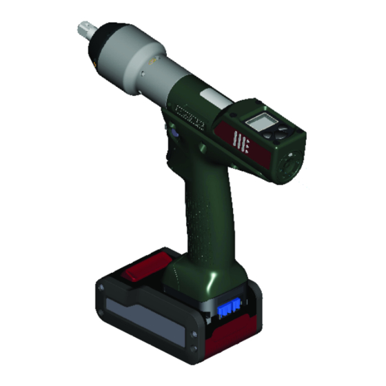
E-Pulse Cordless Nutrunner
Product Instructions
Part number
6151661870
WARNING
Printed Matter No. 6159929740_EN
Issue No.
01
Date
12/2020
Page
1 / 28
Advertisement
Table of Contents

Related Manuals for Desoutter BLRTA045-3990-10S


Summary of Contents for Desoutter BLRTA045-3990-10S
- Page 1 Page 1 / 28 E-Pulse Cordless Nutrunner Product Instructions Model Part number BLRTA045-3990-10S 6151661870 Download the latest version of this document at http://www.desouttertools.com/info/6159929740_EN WARNING Read all safety warnings and instructions Failure to follow the safety warnings and instructions may result in electric shock, fire and/or serious injury.
-
Page 2: Table Of Contents
Table of Contents Product Information .......................... 3 General Information......................... 3 Warranty.......................... 3 Website .......................... 3 Information about spare parts .................... 3 Dimensions .......................... 3 CAD files .......................... 4 Overview ............................ 4 General overview ......................... 4 Product description ...................... 5 Technical data........................ 6 Accessories.......................... 7 Installation.............................. 8 Installation Instructions........................ 8 Inserting the battery pack..................... 8 How to connect the tool to CVIMONITOR................ 8 How to install optional accessories .................. 9 Operation.............................. 10 Configuration Instructions...................... 10... -
Page 3: Product Information
• The product warranty relies on the correct use, maintenance, and repair of the tool and its component parts. • Damage to parts that occurs as a result of inadequate maintenance or performed by parties other than Desoutter or their Certified Service Partners during the warranty period is not covered by the warranty. -
Page 4: Cad Files
General overview BLRTA tools are e-Pulse cordless pistol nutrunners. They are hand-held by the operator and powered by a Desoutter battery pack. On delivery, the tool display is protected by a password. Tools are delivered with 6 Psets which are configurable from the tool display or from CVI CONFIG. -
Page 5: Product Description
Product Information Target torque Rundown speed Pulse amplitude Product description In the following illustration, the tool is shown without its protective cover. Output drive Front light Trigger Reverse button Reporting LEDs Battery pack footprint Display Programming buttons 12/2020 5 / 28... -
Page 6: Technical Data
Product Information Technical data Voltage (V) 18 V or 36 V Power consumption 500 W Output drive Model Type BLRTx-10S Sq. 3/8" BLRTx-4Q Hex. 1/4" F BLRTx stands for BLRTA/BLRTC. Output retaining type Model Type BLRTx-10S through hole BLRTx-4Q quick-change chuck BLRTx stands for BLRTA/BLRTC. -
Page 7: Accessories
Product Information Storage and use conditions Storage temperature -20 to +70 °C (-4 to +158 F) Operating temperature 0 to 45 °C (32 to 113 F) Storage humidity 0-95 % RH (non-condensing) Operating humidity 0-90 % RH (non-condensing) Altitude up to 2000 m (6562 feet) Usable in Pollution degree 2 environment Indoor use only... -
Page 8: Installation
Installation Installation Installation Instructions Inserting the battery pack In the following illustration, the tool is shown without its protective cover. Insert the battery pack in front or behind the tool until a locking sound can be clearly heard. There is no ON/OFF switch: the tool is ready to operate as soon as a battery pack is mounted. When the tool is powered on, tool LEDs are blinking. -
Page 9: How To Install Optional Accessories
Installation Click Select to select the tool. How to install optional accessories Refer to the user manual dedicated to the accessory available at https://www.desouttertools.com/resource-centre. 12/2020 9 / 28... -
Page 10: Operation
Operation Operation Configuration Instructions How to configure the tool Icons and buttons The password is enabled. The password is disabled. Press the button "Validate/Run reverse". Press the right button. Press the left button. "Validate/Run reverse" button Right button Left button Validate Save Quit... - Page 11 Operation Go to Enter password, then Pset password, use the buttons to display "1", save and and validate. The red padlock turns green. The procedure is the same to disable the Maintenance password. How to set up new passwords To set new passwords, current passwords must be disabled and the green padlock displayed. Go to the main screen.
- Page 12 Operation Press this button during 2 seconds. Press this button to reach Configuration. Go to Torque unit, use the buttons to select the torque unit and validate. How to set up the reverse mode Go to the main screen. Press this button during 2 seconds. Press this button to reach Configuration.
-
Page 13: Additional Pset Parameters
Operation Parameter Description Final speed (or Downshift speed) Speed applied from "Downshift torque" to the motor stop. Max. time 30 sec by default. The tool stops when the time is reached. Motor control Starting at the "Start" signal, the tool runs with a programmed acceleration up to "Rundown speed". The tool keeps running at "Rundown speed". -
Page 14: Operating Instructions
Operation Tighten your application Final torque ≥ target torque Increase Pulse amplitude by 10% Some pulses appear or are noise perceptible Decrease Rundown speed by 10% Number of pulses Too low Decrease Pulse amplitude by 10% Too high Rundown speed ≥ 100% Increase Rundown speed by 10% Increase Pulse amplitude by 10% Setup OK for the joint... - Page 15 Operation WARNING Risk Of Injury As the reaction force increases in proportion to the tightening torque, there is a risk of severe bodily injury of the operator as a result of unexpected behavior of the tool. Make sure that the tool is in perfect working order and the system is programmed correctly. ►...
- Page 16 Operation Angle control with torque monitoring Abort torque Max. torque Min. torque Angle threshold Pset start torque Min. angle Target angle Max. angle For tools running in severe applications, it may happen that reports are null when the battery is low. Reporting LEDs Green Yellow...
- Page 17 Operation LED color Description Action to do Yellow Incomplete rundown Tighten again. Yellow and red (orange) Reject report Loosen and tighten again. Above max. limits Remove and replace the fastener. How to reverse the rotation In the following illustration, the tool is shown without its protective cover. Changing bits How to wake up the tool The tool display switches off automatically after 2 minutes of inactivity.
-
Page 18: Service
Service Service Firmware version on tool display The firmware version of the tool is displayed in the menu "Maintenance/Tool". AX.YY.ZZ. Additional tool information Total counter Number of pulses done since the manu- facturing of the tool. Tool information from tool display Go to "Maintenance/Tool"... -
Page 19: Read Before Maintenance
Service Read before maintenance WARNING Connection Hazard The tool can start unexpectedly and cause severe bodily injury. Prior to any maintenance task, disconnect the tool. ► Maintenance should be performed by qualified personnel only. Follow standard engineering practices and refer to exploded views for disassembling and reassembling the different parts of the system. -
Page 20: Calibration Via Tool Display
This function is set in the "Maintenance" menu. Enter the Maintenance password in the "Configuration" menu. Insert a torque transducer in line with the tool and connect it to any measuring unit from the Desoutter range. Go to "Maintenance/Calibration". Select the number of tightenings required to execute the calibration and press OK. -
Page 21: Checking Before Putting Back Into Service
It is mandatory to calibrate the tool equipped with the fixed accessory before use. Upgrading tool firmware Click this icon. Click Upgrade tool firmware. Contact your Desoutter representative to get the last firmware version. Follow the instructions on screen. 12/2020 21 / 28... -
Page 22: Troubleshooting
1- The tool tightening counter has been reached. I038 Tool logs 1- Unexpected tool software exception. 2- Log file has been generated by the tool. 3- Contact your Desoutter representative for support. I046 Abnormal battery current 1- Abnormal battery current consumption. Check the Pset settings. - Page 23 2- Check the tool cable is not damaged. W212 Result not stored 1- It is not possible to store the tightening result in the system. 2- Contact your Desoutter representative for support. W216 Current high 1- Maximum current exceeded. 2- Contact your Desoutter representative for support.
- Page 24 2- Replace the battery pack or your configuration. E223 Drive init error 1- Software failure. 2- Restart the system. 3- If the problem occurs again, contact your Desoutter representative for support. E227 Motor stalled 1- Motor stalled (could be missing phase, wrong motor tune or power electronics failure) 2- Try once again.
- Page 28 Original instructions Founded in 1914 and headquartered in France, Desoutter Industrial Tools is a global leader in electric and pneumatic assembly tools serving a wide range of assembly and manufacturing operations, including Aerospace, Automotive, Light and Heavy Vehicles, Off-Road, General Industry.
Need help?
Do you have a question about the BLRTA045-3990-10S and is the answer not in the manual?
Questions and answers