Table of Contents
Advertisement
Quick Links
Application, Installation, & Service Manual
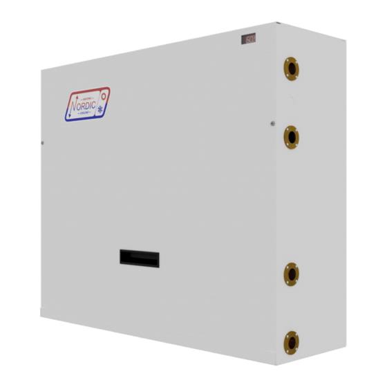
WD-Series
Wall Mounted Domestic Hot Water Water-Source Heat Pump
R134a 60Hz
Maritime Geothermal Ltd.
info@nordicghp.com
P.O. Box 2555, 170 Plantation Road
www.nordicghp.com
Petitcodiac, NB E4Z 6H4
002337MAN-03
(506) 756-8135
ECO 000313:1-Nov-2023
Page 1
002337MAN-03
ECO 000313:
1-Nov-2023
Advertisement
Table of Contents

Subscribe to Our Youtube Channel
Related Manuals for Nordic WD Series


Summary of Contents for Nordic WD Series
- Page 1 Application, Installation, & Service Manual WD-Series Wall Mounted Domestic Hot Water Water-Source Heat Pump R134a 60Hz Maritime Geothermal Ltd. info@nordicghp.com P.O. Box 2555, 170 Plantation Road www.nordicghp.com Petitcodiac, NB E4Z 6H4 002337MAN-03 (506) 756-8135 ECO 000313:1-Nov-2023 Page 1 002337MAN-03 ECO 000313: 1-Nov-2023...
- Page 2 SAFETY PRECAUTIONS WARNING: Ensure all access panels are in place and properly secured before applying power to the unit. Failure to do so may cause electrical shock. WARNING: Before performing service or maintenance on the system, ensure all power sources are DISCONNECTED.
-
Page 3: Table Of Contents
Table of Contents Tables & Documents Startup Procedure ..........3 ............ 14 Pre-start Inspection ............... 14 WD-Series System Description ......4 Unit Startup ................14 General Overview ..............4 Startup Record ..............15 Heat Source: Water Well (Open Loop) ........4 Routine Maintenance .......... -
Page 4: Wd-Series System Description
It is a varia- tion on the geothermal space heating Nordic W and WH-series, in the summer for air conditioning. This tank can be used as a which have long histories of reliable operation. -
Page 5: Installation Basics
Installation Basics Sample Bill of Materials Unpacking the Unit Although not exhaustive, following is a list of materials needed When the heat pump and A-231 kit reach their destination, for a typical installation: they should be unpacked to determine if any damage has occurred during shipment. -
Page 6: Wiring
Wiring Heat Pump Power Supply Connections DHW Circulator Wiring The DHW circulator pump is built in to the heat pump, so The unit has a 7/8” knockout for main power supply con- no field wiring is required. nection to the electrical box. There are also a 7/8” knockout and a 1/2”... -
Page 7: Dhw Aquastat
DHW Aquastat Optional Ground Loop Aquastat Since this aquastat is built in, no field wired aquastat or If using the WD-series heat pump where the source temperature probe is required. (ground loop) temperature might seasonally fall below the mini- mum of ~45°F, an additional aquastat may be used to deacti- vate the heat pump to avoid nuisance low pressure safety con- trol trips, and also activate the tank elements or burner to pro- vide DHW heating while the heat pump is disabled. -
Page 8: 002341Cdg - Wd-Series Wiring Connections
ECO 000313:1-Nov-2023 Page 8 002337MAN-03... -
Page 9: 002342Cdg - Ground Loop Lockout Aquastat Connection
ECO 000313:1-Nov-2023 Page 9 002337MAN-03... -
Page 10: Domestic Hot Water Piping
Piping Domestic Hot Water Piping long as possible (e.g. 12 hours) at the flow rate required, and measuring the pumping fluid level to ensure it is still well above The connections for the DHW Loop circuit are 3/4” the submersible pump intake. brass FNPT. -
Page 11: 002339Pdg - Piping Connections (Open Loop Source)
ECO 000313:1-Nov-2023 Page 11 002337MAN-03... -
Page 12: Outdoor Piping - Ground Loop
Outdoor Piping - Ground Loop A closed ground loop is an excellent heat source for the heat pump in warmer climates, where the loop temperature is above 45°F (7°C) year-round. The WD-16 may be piggybacked onto an existing larger spacing heating ground loop, provided it has spare capacity according to its historical temperature data. -
Page 13: 002340Pdg - Piping Connections (Ground Loop Source)
ECO 000313:1-Nov-2023 Page 13 002337MAN-03... -
Page 14: Startup Procedure
Startup Procedure The startup record in this manual is used in conjunction with this startup procedure to provide a detailed record of the inst a llation. A completed copy should be left on site, a copy kept on file by the installer, and a copy should be sent to Maritime Geothermal Ltd.. Pre-Start Inspection DHW Loop: 1. -
Page 15: Startup Record
Startup Record Sheet - WD Series Installation Site Startup Date Installer City Company Province Check boxes unless Model asked to record data. Country Serial # Circle data units. Homeowner Name Homeowner Phone # PRE-START INSPECTION DHW System All shut-off valve are open (full flow available) -
Page 16: Routine Maintenance
Routine Maintenance MAINTENANCE SCHEDULE Item Interval Procedure Compressor 1 year Inspect for pitted or burned points. Contactor Replace if necessary. Heat When experienc- Disconnect the loop and flush heat exchang- Exchangers ing performance er with a calcium removing solution. Gener- (DHW Brazed degradation that is ally not required for outdoor closed loops or... -
Page 17: Troubleshooting Guide
Troubleshooting Guide Repair procedures and reference refrigeration circuit diagrams can be found at the end of the troubleshooting guide. STEP 1: Remove the cover and verify that there is power to the heat pump, referring to POWER SUPPLY TROUBLESHOOTING below. If ok, proceed to STEP 2. STEP 2: Check to see if there is a fault code on the control board. - Page 18 BUILT-IN AQUASTAT TROUBLESHOOTING Fault Possible Cause Verification Recommended Action No display on No power to heat pump. 230VAC is not present across L1 and Check breaker, wiring, and discon- L2/L3 of the compressor contactor. nect switch. aquastat (if used) Faulty aquastat. 230VAC is present across L1 and L2/L3 Replace aquastat.
- Page 19 COMPRESSOR TROUBLESHOOTING Fault Possible Cause Verification Recommended Action Compressor will Faulty control board. Measuring from C on the terminal strip, Replace control board. verify there is voltage at Y, HP1, HP2, not start LP1, LP2, and both flow pins but no volt- age present at CC.
- Page 20 OPERATION TROUBLESHOOTING Fault Possible Cause Verification Recommended Action High Discharge Aquastat setpoint too high. Verify aquastat setting. Lower aquastat setpoint to recom- mended value of 140°F (60°C). Pressure Low or no indoor loop flow. Delta T across the Indoor Loop ports Verify built-in circ.
- Page 21 OPERATION TROUBLESHOOTING Fault Possible Cause Verification Recommended Action High Suction TXV adjusted too far open. Verify superheat. It should be between Adjust TXV to obtain 8-12°F (3-6°C) 8-12°F (3-6°C). Superheat will be low if superheat. Pressure TXV is open too far. (may appear to not be pumping) TXV stuck open.
-
Page 22: Repair Procedures
Repair Procedures Pumpdown Procedure 1. Connect the refrigerant recovery unit to the heat pump’s internal service ports via a refrigeration charging manifold and to a recovery tank as per the instructions in the recovery unit manual. Plan to dispose of refrigerant if there was a compressor burnout. -
Page 23: Compressor Replacement Procedure
Compressor Replacement Procedure 1. Pump down the unit as per the Pumpdown Procedure above. If there was a compressor burn out (motor failure), the refrigerant cannot be reused and must be disposed of according to local codes. 2. Disconnect piping. 3. -
Page 24: Model Specific Information
Model Specific Information Table 7 - Shipping Information Table 8 - Refrigerant Charge WEIGHT DIMENSIONS in (cm) MODEL Refrigerant Oil Type MODEL lb. (kg) WD-16 R134a - Oil capacity is marked on the compressor label. WD-16 160 (73) 38 (97) 16 (41) 33 (84) - Refrigerant charge is subject to revision;... -
Page 25: Performance Tables
Performance Tables WD-16-H-B-1S R134a, 60 Hz, QXEM-B18A130 OUTDOOR LOOP (Water) ELECTRICAL INDOOR LOOP (Water) Evap. Flow Delta T Heat Abs. Compressor Input Cond. Flow Delta T Heating (°F) Temp. (gpm) (°F) (°F) (Btu/hr) Current (A) Power (W) (°F) Temp. (gpm) (°F) (°F) (Btu/hr) -
Page 26: Wiring Diagram (208/230-1-60)
ECO 000313:1-Nov-2023 Page 26 002337MAN-03... -
Page 27: Wiring Diagram - Contactor Kits
ECO 000313:1-Nov-2023 Page 27 002337MAN-03... -
Page 28: Wd-Series Refrigeration Circuit
ECO 000313:1-Nov-2023 Page 28 002337MAN-03... -
Page 29: Dimensions
Dimensions ECO 000313:1-Nov-2023 Page 29 002337MAN-03... -
Page 30: Warranty
This warranty is subject to the following conditions: 1. The NORDIC® heat pump must be properly installed and maintained in accordance with MARITIME GEOTHERMAL LTD.'s installation and maintenance instructions.
Need help?
Do you have a question about the WD Series and is the answer not in the manual?
Questions and answers