
Subscribe to Our Youtube Channel
Related Manuals for Starck Sefam S.Box Series


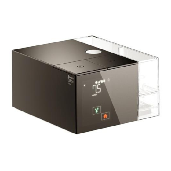
Summary of Contents for Starck Sefam S.Box Series
- Page 1 PTIONAL HEATED UMIDIFIER S.Box Range : S.Box™ S.Box™ S.Box™ Duo S.Box™ Duo Service Manual...
- Page 2 Manufacturer: Manufacturing and technical service location: SEFAM SEFAM 144 AV CHARLES DE GAULLE 10 ALLEE PELLETIER DOISY 92200 NEUILLY SUR SEINE 54600 VILLERS-LES-NANCY FRANCE FRANCE TEL: +33 (0) 3 83 44 85 00 www.Sefam-medical.com Technical assistance: TEL.: +33 (0) 3 83 44 85 23 E:mail: technicalservice@sefam-medical.com ▪...
-
Page 3: Table Of Contents
ONTENTS S.Box use manual ..........................4 Maintenance operations ........................4 Views of the device ............................4 Disassembly instructions ..........................5 Assembly instructions ..........................12 Verification, setting et calibration methods ..................20 Pressure Verification ........................... 20 Service menu access SEFAM Analyze ....................21 Pressure and flow sensor calibration ...................... -
Page 4: S.box Use Manual
S.Box use manual Refer to last version of “Physician and Home Care Provider User Manual” for detailed informations about the S.Box range use. réf. M-164DFU00-30 for S.Box réf. M-164DFU05-80 for S.Box C réf. M-164DFU03-90 for S.Box Duo S et Duo ST Maintenance operations Views of the device Figure 2 –... -
Page 5: Disassembly Instructions
Button to unlock humidifier chamber To unlock and remove the humidifier chamber or the or side cover: side cover from the machine. SD card slot: Slot for inserting the SD card. USB connector: Intended for use by your doctor or Home Care Provider. - Page 6 • Handle circuit boards by edges only, • Work on a grounded conductive mat, • Wear a grounded wrist strap, • Store circuit board in a conductive plastic bag. Disassembly instructions • To remove the side cover (fig.1) or the humidifier (fig.2) from the device, Press the button to unlock the cover and at the same time, pull the cover with the integrated handle located under the cover away from the machine.
- Page 7 • Remove the 4 screws of the bottom cover with a T10 tip equipped screwdriver. • Remove the top cover (be careful to the clip connected to the rear cover). • Carefully remove the IP protection from the main board (take care with grooves, tabs and capacitors).
- Page 8 • Unscrew the screw that holds the front panel display with a T6 tip equipped screwdriver (fig.1). • Depress the bottom of the display from its notch and slide the display upwards to remove it (fig.2). Slide display Fig.1 upward Notch Fig.2 •...
- Page 9 • Unscrew the 3 screws on the main board with a T6 tip equipped screwdriver. • Lift the main board slightly and disconnect the pressure/flow sensor and humidifier cables. • Remove the main board from its location. Humidifie Sensor • Unscrew the screw holding the rear panel (Fig.1), remove the rear panel and the elbow seal from its location (Fig.2).
- Page 10 • Unscrew with a screwdriver equipped with a T6 tip and remove the upper frame chassis by passing the turbine cable through the rectangular opening (be careful to the holding clip) (Fig.1). • Remove the pressure/flow sensor (Fig.2). Rectangula Unscrew r opening Hold clip •...
- Page 11 • Remove the humidifier cable from the rib (Fig.1) • Slide the humidifier connector to the right to unlock (1) and remove the humidifier cable from the cover opening (2) (Fig.2). Fig.1 Fig.2 • Remove the tank inlet seal and the tank outlet seal from the bottom cover. Sefam S.Box Maintenance operations ▪...
-
Page 12: Assembly Instructions
Assembly instructions • Prepare the bottom cover. • Insert the humidifier connector in the opening of the bottom cover (1), and then slide it to the left to lock (2) (Fig.1). • Place the humidifier cable behind the rib (Fig.2). Fig.2 Fig.1 •... - Page 13 • Place the tank inlet seal on the bottom cover, with the bevel facing down (1). • Check that the two seals are correctly positioned (The holes of the bottom cover must be covered by the seals). • Place the turbine chassis on the bottom cover by sliding it into the tank inlet seal (1) while lifting the tank outlet seal (2).
- Page 14 • Assemble the cable on the pressure/flow sensor. • Place the pressure / flow sensor against the air outlet seal (mark the direction of the sensor with the arrow on the sensor ( • Place the air outlet seal locating on the turbine chassis location. Locating •...
- Page 15 • Place the elbow seal and the air inlet seal on the rear cover • Engage the elbow seal on the pressure/flow sensor, while positioning the 3 ribs at the bottom of the rear cover on the bottom cover. • Screw with a T6 tip equipped screwdriver, until it locks.
- Page 16 • Place the connector board in its back cover slot (insert the connectors in their slots). • Place the accessory connector in the opening of the bottom cover (1) and slide it up to lock (2). • Connect the turbine cable to the connector on the main board (3). •...
- Page 17 • Screw the 3 screws with a T6 tip equipped screwdriver until they are locked. • Screw the connector board with a T6 tip equipped screwdriver until it locks. • Place and slide down the front panel display on the bottom cover and engage the notch in its position.
- Page 18 • Screw the front panel display with a T6 tip equipped screwdriver, until it locks. • Connect the display ribbon into the main board connector (Fig.1). • Lock the connector (Fig.2). Fig.2 Fig.1 • Place the IP protection on the main board. Place the IP protection carefully on the capacitor (Fig.1).
- Page 19 • Place the top cover (check that it is inserted into the rear panel rib). • Close the top cover by tightening the 4 screws with T10 tip equipped screwdriver, until it locks. • Insert the communicating accessory (SEFAM S.Box® modem, SEFAM S.Box® Wi-Fi module or PolyLink system) for equipped devices (Fig.1).
-
Page 20: Verification, Setting Et Calibration Methods
Verification, setting et calibration methods Pressure Verification Freqency and required equipment Pressure control can be done once a year (recommended but not mandatory). Required equipment : A calibrated pressure meter 0-30 cm H A Ø 22 or 15mm patient tube. A air stopper (ISO 22 or 15 mm depending tube type) with pressure plug, Pressure control •... -
Page 21: Service Menu Access Sefam Analyze
Service menu access SEFAM Analyze • Open the software SEFAM Analyze, • Connect your S.Box to the computer with a USB cable. • Click on the direct link connection icon • Once the direct login screen appears, press the following key combination: •... -
Page 22: Pressure And Flow Sensor Calibration
Pressure and flow sensor calibration Description and requirements Application cases: The pressure and flow sensor must be calibrated in the following cases: • Any maintenance operation, such as: replacement of the sensor, an equipped chassis or mainboard. • During a periodic pressure check: In case of ineffective automatic offset (see above). Calibration concept: The flow and pressure sensor provides a linear measurement response of the type "y = ax + b", with "b"... - Page 23 Pressure gain setting Required equipment: • A computer with SEFAM Analyze, • A Ø 15 or Ø 22 mm patient tube, • A air stopper (ISO 22 or 15 mm, depending tube type) with pressure plug, • A calibrated differential pressure manometer with the following characteristics : →...
- Page 24 Flow gain setting Required equipment: • A computer with SEFAM Analyze, • A Ø 15 or Ø 22 mm patient tube, • A manual valve (for 120 SLPM ± 3 leakage setting) , • A calibrated flow analyzer with the following features : →...
-
Page 25: Spare Parts
Spare parts Reference Description M-416410-00 S.Box power supply M-316430-03 Side cover S.Box (Ext) M-316420-01 S.Box heated element M-216430-06 S.Box heated humidifier M-216430-15 S.Box Humidifier chamber M-216430-16 S.Box Humidifier chamber base part M-316470-01 Display S.Box (Ext) M-316490-01 Main board S.Box, tested (Ext) - SEE NOTE 1 and 2 M-316450-01 Internal equipped turbine frame (chassis) S.Box V1 (Ext) - SEE NOTE 1 M-316450-11... - Page 26 NOTE 1 : The S.Box V1 chassis is not compatible with machine software versions higher than 1.08. Ver A01.08.00 The machine software version is indicated on SEFAM Analyze main page : Contact the SEFAM after-sales service in case of doubt or need for a software update. WARNING: Failure to comply with this rule will result in a S.Box performance degradation.
- Page 28 Manufacturer: Manufacturing plant: SEFAM SEFAM 144 AV CHARLES DE GAULLE 10 ALLEE PELLETIER DOISY 92200 NEUILLY SUR SEINE 54600 VILLERS-LES-NANCY FRANCE FRANCE : M-164MAT00-10-Version 4 2022-11...
Need help?
Do you have a question about the Sefam S.Box Series and is the answer not in the manual?
Questions and answers