
Related Manuals for Sanhua SEC6X1-HD


Summary of Contents for Sanhua SEC6X1-HD
- Page 1 “寒卫”电子膨胀阀控制器 快 速 安 装 手 册 SEC6X1-HD 寒卫 II-SEC( )-MU-R2401 P02~09 SEC6x1-HD EEV Controller Quick Installation Manual II-SEC(HD)-MU-R2401 P10~25...
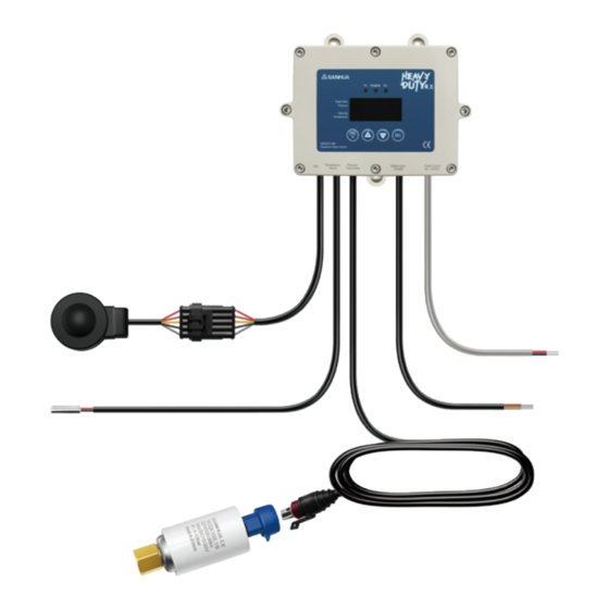
- Page 2 II-SEC( 寒卫 )-MU-R2401 一 . 安装及接线 螺钉安装 通 过 控 制 器 上 下 方 共 3 个 安 装 孔, 用 3 个 M4x6 螺 钉 安 装。 SEC6X1-HD 采用全密封设计,可直接固定于冷风机钣金上 ( 内外均 可 ) 或者冷间内其他就近位置。 塑壳上 8 个螺钉禁止拆卸,否则将影响产品的密封性。 SEC611-HD( 一体式线圈带压力变送器 ) SEC621-HD( 分体式线圈带压力变送器...
- Page 3 引线长度 (mm) 序号 标识 名 称 功 能 备 注 SEC611-HD/ SEC621-HD/ SEC631-HD SEC641-HD L ( 红 ) 交流 220Vac(85Vac ~ 264Vac) ❶ 供电电源 Power Supply N ( 黑 ) 50/60Hz 启停 RUN ( 灰 ) RUN 与 GND 组成开关输入 融霜...
- Page 4 黑 蓝 橙 红 远程显示器(选配)接线示意图如上所示 外形尺寸 84(W)×36(H)×19.4(D)mm 开孔尺寸 71(W)×30(H)mm 远程显示器与控制器之间的通讯电缆建议采用 双绞屏蔽线 2P×24AWG 以上 建议将温度传感器与压力变送器安装尽量靠近蒸发器 出口,距离蒸发器出口不超过 0.5m 的吸气管路上,可 防止环境温度和压降干扰过热度的计算。 二 . 按键及操作 ★默认显示当前吸气过热度 SH;按【+】或【-】键可切 换显示内容,查看完其他实时数据,无按键操作 1 分钟 之后自动回归“SH”数据显示。 定义 描述 定义 描述 通讯正常则 LED 常亮 长按进入参数设置模式或短按返回上一层 启停开关闭合则 LED 常亮 增加或上翻 按钮 融霜开关闭合则...
- Page 5 g. 修改完所有参数后,长按 3 秒保存设置, 此时数码管显示“---”,1 秒后,自动返 回正常运行界面。 备注: 1. 如果密码输入错误或者没有输入密码,则 可以进行参数查询,但不能进行参数更改; 2. 输入密码正确进入参数设置后,10 分钟内 可以进行参数设置,10 分钟后须重新输入 密码;进入参数设置操作后,若 3 分钟内 无操作则自动退出到正常运行显示界面。 三 . 主要参数设置 3.1 控制器模式选择 地址 4x(代码) 工作模式 设定数值 描述 接线 - 过热度自动控制模式 控制模式 0 - 温度/压力信号确保过热度稳定 56(C16) - 阀门手动控制模式 控制模式...
- Page 6 3.2 制冷剂选择 位于参数表 中 4.Pr 地址 4x 代码 描述 默认值 范围 制冷剂选择 -1 ~ 35 5(R507) 14(R744-CO 注 : 对于 SEC611-HD 和 SEC621-HD,d01 默认值为 5(R507);对于 SEC631-HD 和 SEC641-HD,d01 默认值为 14(R744-CO )。 目前控制器中有 36 种常用制冷剂可供选择 代码 制冷剂 代码 制冷剂 代码 制冷剂 代码...
- Page 7 1) SEC611-HD 和 SEC621-HD 的报警默认值为 1。 SEC631-HD 和 SEC641-HD 的报警模式默认值为 0。 2) SEC611-HD 和 SEC621-HD 的 MoP 报警值的 Max. 和默认值分别为 50.0 和 9.0。 SEC631-HD 和 SEC641-HD 的 MoP 报警值的 Max. 和默认值分 别为 99.9 和 38.7。 3) SEC611-HD 和 SEC621-HD 的取消 MoP 报警的 Max. 和默认值分别为 50.0 和 8.0。 SEC631-HD 和 SEC641-HD 的取消 MoP 报警的 Max. 和默认 值分别为...
- Page 8 地址 4x 描述 代码 单位 间隔 默认值 Min. Max. 电子膨胀阀开度最小百分比 传感器(压力和温度)输入滤波时间 99.9 电子膨胀阀强制开阀比例 -1 (OFF) 100.0 -1 (OFF) 0~5,0 表示轮流显示 1= 过热度 显示模式 2= 蒸发器出口压力 ᅠ3= 膨胀阀开度 4= 蒸发器出口温度 ᅠ5= 饱和温度 0= 常开 1= 开关信号控制 启停方式 2= 通讯信号控制 MODBUS ID 设置 0=4800,NONE,1 1=9600,NONE,1 2=19200,NONE,1 3=38400,NONE,1 4=4800,NONE,2...
- Page 9 2、地址 109 报警标志位 标志位为 0 表示无故障 / 保护;标志位为 1 表示有故障 / 保护。 六.通讯状态表 地址 4x 功能 单位 类型 字数 SEC6X1-HD 显示 RS485 通讯 当前过热度 模拟信号 ×10 INT 16 当前压力 模拟信号 -1.0 ~ 99.0 ×100 INT 16 膨胀阀开度 模拟信号 0.0 ~ 100.0 ×10...
- Page 10 SEC6x1-HD EEV Controller Quick Installation Manual II-SEC(HD)-MU-R2401 -10-...
-
Page 11: Installation And Wiring
1. Installation and Wiring Screw installation Use 3pcs M4x6 screws through 3 mounting holes to install controller. SEC6X1-HD has fully hermetic design and can be directly installed on the sheet metal of the air cooler (both inside and outside) or other nearby locations in the cold room. - Page 12 Cable Length(mm) Print Description Function Remarks SEC611-HD/ SEC621-HD/ SEC631-HD SEC641-HD ( ) ① 220Vac ~ Power Supply ( ) (85Vac 264Vac) 50/60Hz Black START/STOP RUN Connect with GND (Grey) Defrost DEF ( ) Connect with GND Yellow Digital Input ① /RS485 Connect with RUN, defrost ②...
- Page 13 Figure 1 Figure 2 Figure 3 L / DC24V+ N / DC24V- Figure 4 Passive input connection Figure 5 Active input connection Remote display (optional) wiring diagram shown as above: × × Dimension 84(W) 36(H) 19.4(D)mm × Hole size 71(W) 30(H)mm The communication cable between the remote display and the controller recommends a twisted pair ×...
-
Page 14: Button And Operation
It is recommended to install the temperature sensor and pressure transmitter on the suction line within 0.5m from the outlet of the evaporator to avoid the interference of the superheat calculation from the environmental temperature and pressure drop. 2. Button and operation ★... - Page 15 Definition Description Definition Description ℃ Display temperature/ Display current EEV /bar OPEN pressure unit opening ★ Display current suction Display suction TEMP superheat temperature Display saturated ᅠ Display current temperature PRESS evaporating pressure corresponding to PRESS suction pressure Running state Long press Correct password?
-
Page 16: Main Parameter Settings
, a. In the power-on state Long press for more than 3s, enter to parameter setting mode. ( ) b. When screen displays , press until screen shows 5 default password , press to enter to parameter list. ᅠ、 ( )... - Page 17 Holding Register Working SETUP Description Wire connection Address mode MODE (code) • Valve manual operation mode ( ) Controlling • Control valve opening ratio mode 1 by pressing on the panel • Driving mode ( ) Controlling • Driving by external mode 2 1-5V analog signal •...
- Page 18 3.2 Refrigerant selection In parameter list 4.Pr Holding Register Address Code Description Default value Range 5 (R507) Refrigerant selection -1~35 14 (R744-CO For SEC631-HD and SEC641-HD, default value of d01 =14(R744). For SEC611-HD and SEC621-HD, default Note: value of d01 =5 (R507). There are a total of 36 refrigerants in the controller for selection Code Refrigerant...
-
Page 19: Parameter Table
4. Parameter Table 4.1 Table1.Pr Address Description Code Unit Interval Min. Max. Default Temperature / superheat setting value 30.0 initial opening degree Initial opening durance time P: Proportional increase 99.9 I: Integral time D: Differential coefficient time Low superheat alarm mode 0=N/A 1=Automatic reset Low superheat alarm value 30.0... - Page 20 4.2 Table 2.Pr Address Description Code Unit Interval Min. Max. Default Anti-freezing alarm mode 0=N/A 1=Automatic Reset ℃ Anti-freezing alarm value Anti-freezing alarm delay time/second ℃ Cancel anti-freezing alarm ( ) Select pumpdown and delay time Reserved Pressure setting point to stop pumping down (...
- Page 21 Address Description Code Unit Interval Min. Max. Default EEV opening when sensor fails Defrosting signal control enabled 0= Disabled 1=Enabled start/stop signal control enabled 0= Disabled 1=Enabled 0=Automatic superheat control 1=EEV Manual operation Controlling Mode (Shall power restart) 2=Driving Mode 3=Temperature Controlling Mode 0=external signal...
- Page 22 Holding Register Description Code Unit Interval Min. Max. Default Address EEV min. opening percentage Sensor(pressure and temperature) 99.9 input filtering time Forced EEV opening ratio -1 (OFF) 100.0 -1 (OFF) 0= Alternatively Display 1=Superheat 2=Evaporator outlet pressure Display Mode 3=Expansion valve opening 4=Evaporator outlet temperature 5=Saturated temperature 0=Normally open...
-
Page 23: Alarm Display
4.5 Model Code (Read-only.) Address Description Code Unit Interval Min. Max. Default Max. suction pressure AD Min. suction pressure AD Refrigerant user-defined A1 Min -20000 Max 20000 parameters A1 A2 Min -20000 Max 20000 (R449A) A3 Min -20000 Max 20000 Refrigerant user-defined A1:9975 When the 40062 refrigerant is set to -1,... - Page 24 6. Communication status table RS485 Add. Function Unit Type SEC6X1-HD communication × Present Superheat Analog INT 16 ~ × Present pressure Analog INT 16 -1.0 99.0 ~ × EEV opening ratio Analog INT 16 100.0 ℃ ~ × Present temperature...
-
Page 25: Technical Parameters
7. Communication 1. Support standard RS485 Modbus RTU protocol (2-wire half-duplex), with a maximum of 31 cascades. It is Ω recommended that the last controller be connected to the terminal with a resistance of 120 2. Use twisted-pair shielded cables (2P x 24AWG is recommended) for communication cables. The shielded cables at both ends of the cables must be grounded separately.
Need help?
Do you have a question about the SEC6X1-HD and is the answer not in the manual?
Questions and answers