Table of Contents
Advertisement
Quick Links
SD-590C
Please note that the slight noise when the computer unit shakes is the built-in ball switch, which is a
normal phenomenon caused by the wireless automatic wake-up function design.
FUNCTIONS ILLUSTRATIONS
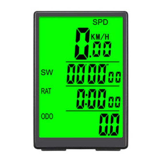
-SPD CURRENT SPEED
-ODO ODOMETER
-DST TRIP DISTANCE
-MXS MAXIMUM SPEED
-AVS AVERAGE SPEED
-TTM TOTAL TRIP TIME
-TM TRIP TIME
-RAT RIDING ALL TIME (SINGLE TRIP TIME)
-CLK CLOCK 12H/24H
-SW STOPWATCH
-Th TEMPERATURE
-MAX Th MAXIMUM TEMPERATURE
-MIN Th MINIMUM TEMPERATURE
-TM UP TRIP TIME COUNT UP
-TM DN TRIP TIME COUNT DOWN
WHAT IS IN THE PACKAGE
2
1
3
COMPONENT ILLUSTRATIONS
Computer unit and mount installation
1
Insert computer unit
in to the mount.
Installation diagram of
magnet and Sensor
INSTRUCTION
Computer unit interface
SPEED
TIME
SET
MODE INSTRUCTION
After inserting the battery, the screen enters the total distance/time mode. Press the MODE button to cycle through single
distance/time mode, count up/down mode and fat/calorie mode in turn. In the total distance/time mode, count up/down
mode and fat/calorie mode, it will automatically return to the single distance/time modeafter 8 seconds of no operation.
ODO / TTM MODE
MALFUNCTIONS AND REASONS
1.The speedometer shows 0 km/h while riding.
Improper magnet/sensor alignment, or the distance between
the computer and the sensor is more than 80cm.
2.The speedometer shows wrong values.
Take out the battery and reset it after 10 seconds.
3.Black display
Avoid exposing the device to direct sunlight or high temperature for too
long. Let it cool down in the shade for a while.
4.Display shows incomplete figures.
Poor battery contact or dead battery .Check the installation of the battery or change a new battery.
5.Display readout fades out
The battery voltage is low, change a new battery.
V1.0
4
5
6
2 Mount the mount
shoe on to the
handlebar.
To attach the speedometer sensor, use the ties to secure it to the front
fork. Make sure the computer and the sensor are on the same side of
the fork and no more than 60cm apart. The sensor should have an
arrow pointing at the magnet. Follow the figure to install the magnet on
a spoke. The gap between the sensor and the magnet should be 3 mm.
3mm
FRONT
MAINTENANCE ALERT
COMPARATOR
LOW BATTERY INDICATOR
MODE
DST / TM MODE
-TRIP UP TRIP DISTANCE COUNT UP
-TRIP DN TRIP DISTANCE COUNT DOWN
-CAL CALORIE
-FAT FATBURN
-COMPARATOR
-Km/Mile SELECTION
-SLEEP MODE
- MAINTENANCE ALERT
- SETTING TYRE CIRCUMFERENCE
-SETTING LAST VALUE OF ODOMETER/ODO
-SETTING TTM
-COMPUTER LOW BATTERY INDICATOR
-SENSOR LOW BATTERY INDICATOR
- AUTO BACK LIGHT
-WIRELESS AUTO WAKE UP
- AUTO ON/OFF
1
Computer
2
CR2032 Battery
3
Magnet
4
Mounting Shoe
5
Sensor
6
Ties
3
Tighten nut to
scure the unIt.
The magnet is designed for spokes
that are less than 2mm thick
BACK
COUNTUP / DOWN MODE
i n
C o
Open
C
lose
Pass bicycle spokes through the
plastic hole on the bottom of the
magnet and tighten to secure
Notice
BATTERY
COVER
COMPUTER &
MOUNTING
SHOE TRIGGER
CAL / FAT MODE
Advertisement
Table of Contents

Subscribe to Our Youtube Channel
Related Manuals for SunDING SD-590C


Summary of Contents for SunDING SD-590C
- Page 1 SD-590C V1.0 Please note that the slight noise when the computer unit shakes is the built-in ball switch, which is a normal phenomenon caused by the wireless automatic wake-up function design. FUNCTIONS ILLUSTRATIONS -SPD CURRENT SPEED -TRIP UP TRIP DISTANCE COUNT UP...
- Page 2 Computer Unit SettIng Enter Setting Mode TIRE SIZE CIRC 12x1.95 In any mode,Long press SET+MODE button for 3 seconds to enter setting mode. 14x1.75 1055 TEMPERATURE UNIT (C/F°) SETTING 16x1.50 1185 16x2.00 1245 After enters setting mode, press the MODE button to select between 17x1-1/4 1340 Celsius or Fahrenheit .
Need help?
Do you have a question about the SD-590C and is the answer not in the manual?
Questions and answers