Table of Contents
Advertisement
Quick Links
FPMA-HAC100
FPMA-HAC100HC
EN
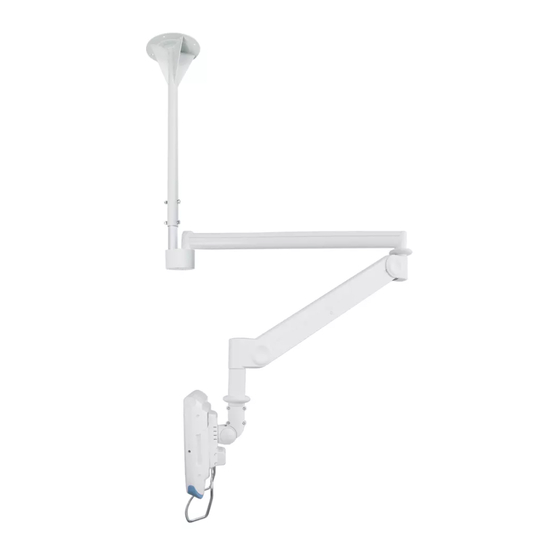
Medical mount
NL
Medische steun
DE
Medizinische Halterung
FR
Support médical
IT
Supporto medico
ES
Soporte médico
PT
Suporte medico
DK
Medicinsk beslag
INSTRUCTION MANUAL
NO
Medisinsk feste
SE
Medicinskt fäste
FI
Medical teline
PL
Uchwyt medyczny
CS
Držák pro lékařské účely
SK
Držiak na lekárske vybavenie
RO
Suport medical
WWW.NEOMOUNTS.COM
Advertisement
Table of Contents

Subscribe to Our Youtube Channel
Related Manuals for NeoMounts FPMA-HAC100


Summary of Contents for NeoMounts FPMA-HAC100
- Page 1 INSTRUCTION MANUAL FPMA-HAC100 FPMA-HAC100HC Medical mount Medisinsk feste Medische steun Medicinskt fäste Medizinische Halterung Medical teline Support médical Uchwyt medyczny Supporto medico Držák pro lékařské účely Soporte médico Držiak na lekárske vybavenie Suporte medico Suport medical Medicinsk beslag WWW.NEOMOUNTS.COM...
-
Page 2: Before Starting Assembly
Only if required, all fastening hardware can be replaced by the installer at their own risk, based on the requirements of the ceiling compo- sition; Neomounts shall not be held liable if any fasterning hardware supplied by third parties fails to sufficiently secure the ceiling mount to the ceiling. - Page 3 PARTS 1. (x1) 2. (x1) 14. (x1) 3. M4x12 (x4) 15. (x4) 16. (x2) 4. M6x30 (x4) 17. (x1) 5. M4x25 (x4) 18. 17 mm (x2) 19. 3 mm (x1) 6. (x4) 20. (x1) 7. 2,5 mm (x1) 21. (x2) 8.
-
Page 4: Arm Operation
ARM OPERATION... - Page 5 POSITIONING Right view Unit: mm SOLID RC WALL...
- Page 6 SERVICEABLE RANGE Range at +20 - Top view Unit: mm SOLID RC WALL Range at -60 - Top view Unit: mm SOLID RC WALL...
- Page 7 CEILING ASSEMBLY Unit: mm NOTE: use level gauge or protractor to help the wall mount installation SOLID RC WALL SOLID RC WALL ± 1 SOLID RC WALL SOLID RC WALL SOLID RC WALL If the wall plate is not levelled after installation on the wall, please use washers to fill the...
- Page 8 STEP 1 Install the ceiling mount firmly to a solid ceiling 1. Disassemble the ceiling mount and the adjustable pole. 2. Choose the exact place you want to fix the ceiling mount on the ceiling and mark the drill holes. 3.
- Page 9 STEP A Install the ceiling cover If the upper pole hangs below a suspended ceiling, remove the ceiling cover spacer and push the ceiling cover up to the ceiling. Insert the two screws using the supplied Allen key to secure. SOLID RC CEILING Push the ceiling cover 26.
- Page 10 STEP 2 1. Place the bearings onto the spindle. 2. Place the arm onto the spindle. 3. Manage the cables well and make sure that the C-clip is fitted into the groove of the spindle securely, so the fixed section of the arm cannot be pulled out from the mount while adjusting the arm.
- Page 11 STEP 3 Adjust the height 1. Put the adjustable pole inside the ceiling mount. 2. Fix the pole at the desired height by wrench with 2 screws, 2 screw bushings, 2 washers and 2 nylon nuts. SOLID RC CEILING 18. 17 mm (x2) 22.
- Page 12 NOTE Please make sure this joint is in a vertical 90 angle. ± 1 ± 1...
-
Page 13: Cable Assembly
CABLE ASSEMBLY PARTS rotating cover-L front cable cover rotating cover top cable cover middle cover-1R middle cover-1L end cover-2L end cover-2R VESA cable cover-S grab handle... - Page 14 STEP 1.1 Remove the cable covers. Remove the VESA cable cover with a screw driver (not provided), as shown. Save the screws for reattachment after the monitor installation. Slide the cable cover out of the arm slot carefully, as shown.
- Page 15 STEP 1.2 Run the cables through the arm. Assemble the cable wrapper. 12. Cable wrapper (x1) 13. Cable tie (x4) 15 cm • The VESA adapter must be moved entirely down to put the cable through. • Allowing for arm movement, it is suggested to keep at least 15 cm of cable left from the VESA adapter.
- Page 16 Please note that the cable should be placed under the spring. Please note that the screw has to go through the spring. Support tools...
-
Page 17: Monitor Assembly
MONITOR ASSEMBLY STEP 1.1 Remove the back cover utilizing a screw driver (not included), as shown and pull out the cable in order to install the monitor. NB. Please save the screws for reattachment of the cover after monitor installation. STEP 1.2 Fix the monitor on the VESA mount, using the Allen key and screws. - Page 18 STEP 1.3 Connect the cable to the monitor Connect the cables to the monitor, complete the circuit and replace the VESA cable cover-B or VESA cable cover-S. STEP 1.4 Fix the handle bar 1. Insert the handle bar into the 2 holes on the bottom of the VESA interface. 2.
- Page 19 REPLACEMENT OF THE ARM COVERS Follow the order as below to assemble the covers. Replace the adjuster covers as shown.
- Page 20 Use the Allen key provided to adjust the weight capacity. Turn the Allen key in a clockwise direction for more weight and in counterclockwise direction for less weight. Loading: FPMA-HAC100: 1~6 kg FPMA-HAC100HC: 6~12 kg • The products loading capacity is based on the monitors’ center of gravity less than 3 cm from the end of the VESA interface.
- Page 21 ADJUSTING UNIVERSAL JOINT TENSION When assembling the arm with monitors of different weight, you may find that the tension of the universal joint needs to be adjusted to ease movement or to maintain the desired monitor position. If so, adjust as follows: 1.
-
Page 22: Safety Notes
SAFETY NOTES • Do not disassemble once assembled. • Make sure that mounting screws are suitable for the horizontal surface and adequate to hold the weight of the arm and the monitor. • Support the monitor and arm throughout assembly and mounting. •... - Page 23 Do not hang or swing on the arm. Do not hold the arm as a support to get up. Do not place unnecessary objects on the arm.
- Page 24 24.02...
Need help?
Do you have a question about the FPMA-HAC100 and is the answer not in the manual?
Questions and answers