
Related Manuals for Clearfield FieldSmart FiberFlex 1700

Summary of Contents for Clearfield FieldSmart FiberFlex 1700
- Page 1 FieldSmart FiberFlex 1700 ® Installation Manual ______________________________________________________ Manual 023903 Rev A - Jan 2024...
-
Page 2: Table Of Contents
Installing a Foundation Vault Foundation Vault Requirements Preparing the Site Installing the Foundation Vault Chapter 4: Installing the Cabinet Unpacking the Cabinet Operating Cabinet Doors Preparing the Cabinet for Installation Proprietary Information: Not for use or disclosure except by written agreement with Clearfield. - Page 3 FieldSmart FiberFlex 1700 ® Installation Manual __________________________________________________________ Installing the Cabinet on a Concrete Pad Lifting Eyes Joining Cabinets Chapter 5: Installing Local AC Power Installing the Cabinet Ground Connection Installing AC Power (220-240 VAC) Chapter 6: Installing Outside Plant Cables Bonding Cable Sheaths Installing Fiber Cable Installing Outside Plant Fiber Cable...
- Page 4 Ice Removal on Cabinet Doors Replacing AC Breakers Replacing Rectifier Modules Replacing Batteries Replacing a Battery Heater Appendix A: Reference Information Supported Batteries Standard Warranty Proprietary Notice Technical Support Proprietary Information: Not for use or disclosure except by written agreement with Clearfield.
-
Page 5: About This Guide
__________________________________________________________ About This Guide This document provides a general installation practice for the Clearfield FiberFlex 1700 outdoor cabinet. This document also provides a general description of the cabinet and its subsystems, guidance for planning, site preparation, power installation, splicing to the outside plant, component installation and expansion, and cabinet maintenance. -
Page 6: Chapter 1: Fiberflex 1700 Product Overview
® Installation Manual _________________________________________________________ Chapter 1: FiberFlex 1700 Product Overview This chapter provides a general description of the Clearfield FiberFlex 1700 outdoor cabinet, including its standard features and options. Topics Covered This chapter provides a general description of the Clearfield... -
Page 7: Cabinet Description
FieldSmart FiberFlex 1700 ® Installation Manual __________________________________________________________ Cabinet Description The Clearfield FiberFlex 1700 cabinet is an Outside Plant (OSP) Cabinet designed to house and protect network electronics equipment. Use the FiberFlex 1700 to provide services from a node location. The FiberFlex... -
Page 8: Node Cabinet Description
_________________________________________________________ Node Cabinet Description The Clearfield FiberFlex 1700 cabinet is an environmentally-controlled outdoor enclosure designed to house and protect network electronic equipment. Use the FiberFlex 1700 Node cabinet to provide services from a remote location. Clearfield has created three node cabinet configurations. -
Page 9: Cabinet Features
FieldSmart FiberFlex 1700 ® Installation Manual __________________________________________________________ Cabinet Features Standard features of the FiberFlex 1700 cabinet include: Enclosure Design • Environmentally sealed design protects from dust and water intrusion • Designed to GR-487 • Environmentally rated from -40C to +65C (per GR-487 specifications) Equipment Support •... -
Page 10: Cabinet Options
Enclosure Mounting • Clearfield designed pour in place templete to assist when a concrete pad is pre-casted or poured on site for alignment and mount of the plinth. • Vault 60” x 36” x 36” (Third party supplied). -
Page 11: Cabinet Dimensions And Weights
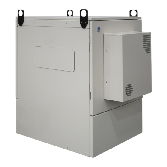
FieldSmart FiberFlex 1700 ® Installation Manual __________________________________________________________ Cabinet Dimensions and Weights The external dimensions of the FiberFlex 1700 cabinet are Height 72” Width 30” Depth 36”. The approximate weight of the FiberFlex 1700 is dependent on configuration and can arrange for 500lbs to 800lbs. Cabinet Views Views of the FiberFlex 1700... - Page 12 Configured cabinets include a battery base compartment for housing one string of front-access VRLA batteries. Battery compartment interior dimensions (for batteries): Opening 13” x 27”, Interior hieght 14.165” Proprietary Information: Not for use or disclosure except by written agreement with Clearfield.
-
Page 13: Chapter 2: Installation Considerations
FieldSmart FiberFlex 1700 ® Installation Manual __________________________________________________________ Chapter 2: Installation Considerations This chapter provides general considerations for cabinet installation. Review this information before starting the cabinet installation process. Topics Covered This chapter covers the following topics: • Installation guidelines • Space requirements •... -
Page 14: Installation Guidelines
• Parking. Whenever possible, the cabinet should be located in an area that provides sufficient parking space for • installation and maintenance vehicles. Proprietary Information: Not for use or disclosure except by written agreement with Clearfield. -
Page 15: Space Requirements
FieldSmart FiberFlex 1700 ® Installation Manual __________________________________________________________ Space Requirements The illustration below shows the cabinet clearance and space requirements. The minimum clearance area around the cabinet site must be free of permanent impediments to allow full swing of the cabinet doors. This area must be kept clear of obstructions at all times to provide adequate access for all installation and maintenance activities. -
Page 16: General Safety Recommendations
CAUTION! Batteries contain a stored charge. Handle batteries with care. ESD ALERT! Beware of electrostatic discharge. Follow standard ESD precautions. Always wear a grounded ESD wristband to avoid damaging the electronic equipment. Proprietary Information: Not for use or disclosure except by written agreement with Clearfield. -
Page 17: Installation Kit
Installation Manual __________________________________________________________ Installation Kit Clearfield supplies an installation kit with the cabinet that includes materials required for installation. The installation kit contents are listed below. Check to verify that your kit contains all of the listed items.: Item Description Telco hex key, 5/16”... -
Page 18: User-Supplied Items
• Leveling shims • Silicone sealant Equipment Bring the following equipment to the installation site: • Digital multi-meter • Optical power meter • Digital multi-function test set Proprietary Information: Not for use or disclosure except by written agreement with Clearfield. -
Page 19: Cabling Requirements
FieldSmart FiberFlex 1700 ® Installation Manual __________________________________________________________ Cabling Requirements Cables supplied to the cabinet must meet the following minimum requirements. Function Facility Requirements Power 6 AWG solid bare copper wire (to earth ground circuit); Ground Copper terminates to ground bar with screw lug Copper 8–10 AWG stranded copper;... -
Page 20: Chapter 3: Preparing The Installation Site
For pad-mount applications, you can construct a concrete pad using the Clearfield cast-in-place template. A composite foundation vault, available from a third-party supplier, can provide easy under-cabinet access. For all mounting configurations, Clearfield requires installation of an earth ground circuit at the installation site to provide lightning protection. -
Page 21: Installing A Ground Circuit
Installing a Ground Circuit Clearfield requires installing an earth ground circuit (earth electrode) at the installation site to provide protection from electric shock for equipment and personnel. The ground circuit may consist of a simple copper rod driven into the earth or a com- plex system of buried rods and wires. - Page 22 FieldSmart FiberFlex 1700 ® Installation Manual _________________________________________________________ Example of PANI-compliant ground ring without a main site ground buss: FiberFlex 1700 Proprietary Information: Not for use or disclosure except by written agreement with Clearfield.
-
Page 23: Constructing A Concrete Pad
Construct a concrete foundation pad for the cabinet at the installation site. Pad construction requires excavating the site, trenching cable conduit, constructing a form, and casting concrete. Use the Clearfield -supplied cast-in-place template to provide exact locations for the mounting studs that anchor the cabinet to the pad and to provide the cable conduit locations. -
Page 24: Assembling The Cast-In-Place Template
Place the two long brackets parallel with each other, flat side down. Step 6: Place the two short brackets between (and perpendicular to) the long members, flat side down, with the conduit entry box bracket on the right. Proprietary Information: Not for use or disclosure except by written agreement with Clearfield. -
Page 25: Preparing The Site
Step 3: Place and tie rebar inside the form elevated above the gravel. Step 4: Place the Clearfield cast-in-place template (see page 14) into the form, guiding the cable conduits through the conduit entry ducts in the template. Step 5: •... -
Page 26: Casting The Pad
Backfill and grade the perimeter area around the pad with soil, as required. Step 8: Trim the cable conduits to a height no more than 4 inches above the pad. Trim Conduits Proprietary Information: Not for use or disclosure except by written agreement with Clearfield. - Page 27 FieldSmart FiberFlex 1700 ® Installation Manual __________________________________________________________ Pad Drawings Use the following drawings for reference during site preparation. Actual pad dimensions may vary by manufacturer. Refer to the manufacturer’s documentation for more information. • Use 2.5-inch conduit (maximum) for outside plant cables. See drawing below for entry locations. •...
- Page 28 Conduit for outside plant cable (fiber). b. Conduit for outside plant cable (fiber). c. Earth ground wire d. Conduit for AC cable Use the Clearfield cast-in-place template to provide precise conduit orientation. Proprietary Information: Not for use or disclosure except by written agreement with Clearfield.
-
Page 29: Installing A Foundation Vault
Foundation vaults ship configured with knockouts for conduit entry and mounting fixtures (threaded inserts) for anchoring the cabinet to the top of the vault. Specific features and dimensions vary by manufacturer and model. Contact your sales representative for Clearfield -certified supplier information. Foundation Vault Requirements When preparing for and installing a foundation vault, observe the following guidelines. -
Page 30: Preparing The Site
Route the earth ground wire through the conduit trench (from the ground electrode). Step 6: Place gravel into the foundation hole to create a level base. The gravel layer should be at least one inch deep, compacted and leveled. Proprietary Information: Not for use or disclosure except by written agreement with Clearfield. -
Page 31: Installing The Foundation Vault
FieldSmart FiberFlex 1700 ® Installation Manual __________________________________________________________ Installing the Foundation Vault Install the foundation vault according to the manufacturer’s instructions (typically supplied with the vault). A general installation practice is described below for reference. Adapt the instructions as needed for local requirements, practices, or conditions. - Page 32 FieldSmart FiberFlex 1700 ® Installation Manual _________________________________________________________ Vault Drawings Proprietary Information: Not for use or disclosure except by written agreement with Clearfield.
- Page 33 FieldSmart FiberFlex 1700 ® Installation Manual __________________________________________________________ Direct: 763.476.6866 • National: 800.422.2537 • www.SeeClearfield.com • techsupport@clfd.net Manual 023903 Rev A - Jan 2024...
-
Page 34: Chapter 4: Installing The Cabinet
® Installation Manual _________________________________________________________ Chapter 4: Installing the Cabinet This chapter describes how to install the Clearfield FiberFlex 1700 cabinet onto its permanent mounting location. Topics Covered This chapter covers the following topics: • Unpacking the cabinet from its shipping crate. -
Page 35: Unpacking The Cabinet
Do not remove the cabinet from the pallet until after it has been delivered to the installation site. However, you can remove the cardboard crating to inspect the cabinet at the staging area, if required. Clearfield recommends keeping the protective packaging in place for transportation. -
Page 36: Operating Cabinet Doors
On a powered cabinet, pull the alarm switch plunger to disable reporting of the intrusion alarm. Note: Do not rotate the switch plunger. Rotating the plunger may damage the switch. Proprietary Information: Not for use or disclosure except by written agreement with Clearfield. - Page 37 Battery Compartment Door The battery compartment door is secured to the equipmart compartment via two spring clips which release the door. Use a Clearfield -supplied telco hex key to open and close the door. To open a battery compartment door Step 1: Open equipment section door.
-
Page 38: Preparing The Cabinet For Installation
Step 5: Remove the nuts from the four bolts securing the cabinet to the pallet. The bolts are located at the bottom four corners of the battery compartment. Proprietary Information: Not for use or disclosure except by written agreement with Clearfield. -
Page 39: Installing The Cabinet On A Concrete Pad
ALERT! Isolation mat usage is mandatory for concrete pad instal- lations. Failure to use the supplied isolation mat can accelerate cabinet corrosion and may void the Clearfield cabinet warranty. Before installing the cabinet, verify that the doors are locked in the open position (wind brace engaged). - Page 40 Note: If properly aligned, the entry ducts should slide down over the conduits as the cabinet lowers. If neces- sary, trim the conduit down to a height that enables it to pass into the entry duct. Proprietary Information: Not for use or disclosure except by written agreement with Clearfield.
-
Page 41: Lifting Eyes
FieldSmart FiberFlex 1700 ® Installation Manual __________________________________________________________ Step 7: Pull the earth ground wire into the cabinet or riser through one of the cable entry ducts. Step 8: Anchor the cabinet or riser to the pad as follows: Site-cast pads with anchor studs from pour-in-place template: a. -
Page 42: Joining Cabinets
Step 3: Place the joining collar into the pass through hole prior to placing the second cabinet (Cabinet B). Proprietary Information: Not for use or disclosure except by written agreement with Clearfield. - Page 43 FieldSmart FiberFlex 1700 ® Installation Manual __________________________________________________________ Step 4: Place Cabinet B onto its plinth, leaving room to flip the lifting eyes. Once completed, push the cabinet into place, aligning the joining collar and securing it in place with the pass through bolts. Step 5: Ensure the lifting eyes of both cabinets are aligned, and secure them together with the provided hardware.
-
Page 44: Chapter 5: Installing Local Ac Power
Install power according to your cabinet configuration type. Topics Covered This chapter covers the following topics: • Installing the cabinet ground connection • Installing local AC power Proprietary Information: Not for use or disclosure except by written agreement with Clearfield. -
Page 45: Installing The Cabinet Ground Connection
You must install the cabinet’s connection to the earth ground circuit before you connect commercial power to the OSP cabinet. Guidelines Clearfield recommends adhering to PANI grounding methods to reduce ground current interaction while following local NEC jurisdiction: • The PANI system divides the ground bar into sections, with one type of conductor in each section: Producers, surge Absorbers, Non-isolated and Isolated (PANI). - Page 46 Attach the earth ground wire’s two-hole lug onto the 3/4-inch ground terminal studs per PANI guidelines. Step 6: Re-connect the nuts to the ground terminal studs and tighten to 26 inch-lbs. of torque. Proprietary Information: Not for use or disclosure except by written agreement with Clearfield.
-
Page 47: Installing Ac Power (220-240 Vac)
FieldSmart FiberFlex 1700 ® Installation Manual __________________________________________________________ Installing AC Power (220-240 VAC) Install 220-240 VAC power as described below. DANGER! High voltage may be present. Risk of electrical shock. Do not apply AC power to the cabinet until the installation process is complete. WARNING! Electrical hazard. - Page 48 FieldSmart FiberFlex 1700 ® Installation Manual _________________________________________________________ AC Load Center Wiring Diagram Proprietary Information: Not for use or disclosure except by written agreement with Clearfield.
-
Page 49: Chapter 6: Installing Outside Plant Cables
FieldSmart FiberFlex 1700 ® Installation Manual __________________________________________________________ Chapter 6: Installing Outside Plant Cables This chapter describes how to install outside plant cables into the cabinet, including fiber plant (fiber-optic cables for transport/uplink). Topics Covered This chapter covers the following topics: •... -
Page 50: Bonding Cable Sheaths
Clearfield recommends that you bond optical fiber cable sheaths at the first entrance to the cabinet/enclosure site only (the splice case, or similar), and then isolate the sheaths in the short run between splice point and the Clearfield equipment cabinet/enclosure ground. The short run can then be bonded on either side (the Clearfield ground bar side or splice point side, but not both) per local practice. -
Page 51: Installing Fiber Cable
FieldSmart FiberFlex 1700 ® Installation Manual __________________________________________________________ Installing Fiber Cable This section describes how to install fiber optic cable into the cabinet, including how to route and groom the outside plant cable and splice fibers for terminating to the equipment. Fiber management guidelines When installing, splicing, and routing fibers in the cabinet, follow these guidelines: •... -
Page 52: Sealing Cable Entry Locations
Note: Alternatively, you may invert the rubber cone gaskets and then inject a foam-type sealant into the cones around the cabling. CAUTION! Only a qualified technician should perform this procedure. Use customer supplied sealant Seal conduit area with sealing to seal entry cones foam provided Proprietary Information: Not for use or disclosure except by written agreement with Clearfield. -
Page 53: Chapter 7: Turning Up The Cabinet Power System
FieldSmart FiberFlex 1700 ® Installation Manual __________________________________________________________ Chapter 7: Turning Up the Cabinet Power System This chapter describes how to turn up and test the cabinet power system. This process includes checking the cabinet ground connection, checking the AC power supply voltage, installing rectifier modules into the rectifier shelf, installing batteries for reserve power, and turning up and testing the DC power system. -
Page 54: Turning Up The Power System
Verify that the ohm meter reads 5 ohms or less. Step 3: If the reading is greater than 5 ohms, check the ground wire connection at the main ground bar, then retest. Proprietary Information: Not for use or disclosure except by written agreement with Clearfield. -
Page 55: Checking The Ac Power Supply Voltage
FieldSmart FiberFlex 1700 ® Installation Manual __________________________________________________________ Checking the AC Power Supply Voltage The cabinet ships from the factory equipped to support 220-240 VAC service. Check the AC power supply voltage as follows. DANGER! High voltage may be present. Only a qualified electrician should perform these procedures. To check 220-240 VAC power supply voltage Step 1: Apply AC power to the cabinet at the local power transfer switch. -
Page 56: Installing Rectifier Modules
Insert the rectifier module into slots from left to right for desired rectification amperage. Step 3: Push firmly on the module to seat it in the slot. Step 4: Repeat steps to install an additional rectifier module. Proprietary Information: Not for use or disclosure except by written agreement with Clearfield. -
Page 57: Installation Of Alarm Wiring
FieldSmart FiberFlex 1700 ® Installation Manual __________________________________________________________ Installation of Alarm Wiring Step 1: Alarms will be connected to alarm block as shown below. Step 2: If customer chooses to purchase and install rectifer plant on their own use the alarm diagram as an example of how to wire alarms. -
Page 58: Installing And Testing Batteries
Note: If the batteries are not fully charged, perform these procedures after charging the batteries. WARNING! In -48V telecom systems, red leads connect to the negative terminal and black leads connect to the positive terminal. Do not reverse the wiring polarities. Proprietary Information: Not for use or disclosure except by written agreement with Clearfield. - Page 59 FieldSmart FiberFlex 1700 ® Installation Manual __________________________________________________________ To install a single string of batteries Step 1: At the rectifier shelf, verify that the battery breaker is OFF. Step 2: Remove the battery compartment door. See Operating Cabinet Doors for instructions. Step 3: Remove the front retainer bracket from the battery tray.
- Page 60 Set the Main breaker to ON and verify that power restores to the rectifier shelf. Step 15: Slide the battery string into the battery tray. Step 16: Replace the battery compartment door. Proprietary Information: Not for use or disclosure except by written agreement with Clearfield.
- Page 61 FieldSmart FiberFlex 1700 ® Installation Manual __________________________________________________________ Turning Up and Testing the DC Power System Turn up and test the cabinet DC bulk power system as described below. To turn up and test the DC power system Step 1: At the AC load center, verify that the Main breaker is ON. Step 2: At the AC load center, switch the 30A Rectifier breaker ON.
- Page 62 At the AC load center, set the Main breaker to OFF. The heat exchanger fans should continue to run. Step 4: At the AC load center, set the Main breaker to ON and verify that power restores to the rectifier shelf. Proprietary Information: Not for use or disclosure except by written agreement with Clearfield.
-
Page 63: Chapter 8: Installing Equipment, Options And Adding Capacity
FieldSmart FiberFlex 1700 ® Installation Manual __________________________________________________________ Chapter 8: Installing Equipment, Options and Adding Capacity This chapter describes how to install optional equipment and components into the cabinet, including expansion components to increase system capacity. The cabinet allows for modular growth of line capacity and supports field installation of all factory options. -
Page 64: Installing A Battery Heater
_________________________________________________________ Installing a Battery Heater For colder climates, Clearfield recommends using an optional battery heater to prevent batteries from freezing and to pro- long battery life. The battery heater is controlled by a thermostat set for the following operation: •... - Page 65 FieldSmart FiberFlex 1700 ® Installation Manual __________________________________________________________ b. Adhere the battery warmer to the inside of the battery warmer mount plate c. Attach the battery warmer ground wire to the battery warmer mount plate ground stud using washer 639- 00002 & nut 637-00026. d.
- Page 66 Route the temperature sensor/thermometer through one of the cutouts in the side channel. The thermostat will later be rested on top of the batteries after they are installed. Proprietary Information: Not for use or disclosure except by written agreement with Clearfield.
- Page 67 FieldSmart FiberFlex 1700 ® Installation Manual __________________________________________________________ Step 4: Install a 15A breaker into the AC Load Center (ACLC) as follows: a. Remove the ACLC face plate. Remove the knockout from the ACLC face plate. Location 8 for the 1st battery warmer breaker, and Location 10 for the 2nd battery warmer breaker.
- Page 68 Excess slack in the cable should be stored in the battery base. e. In the ACLC, attach the ground and neutral wires from the cable to the ground and neutral bars in the ACLC. Proprietary Information: Not for use or disclosure except by written agreement with Clearfield.
- Page 69 FieldSmart FiberFlex 1700 ® Installation Manual __________________________________________________________ f. Attach the black wire to the 15A breaker installed in step 4. g. Reinstall the ACLC faceplate Direct: 763.476.6866 • National: 800.422.2537 • www.SeeClearfield.com • techsupport@clfd.net Manual 023903 Rev A - Jan 2024...
-
Page 70: Installing Fiber Splitters
Installation Manual _________________________________________________________ Installing Fiber Splitters The FieldSmart FiberFlex 1700 will arrive with patch-only panels and splitter trays pre-installed. Install splitters and route the splitter legs as shown. Step 1: Install the WaveSmart Ruggedized Splitter into the splitter tray. Place the splitter body into the tray near the back. - Page 71 FieldSmart FiberFlex 1700 ® Installation Manual __________________________________________________________ Step 3: Install the staging plate into the splitter tray by inserting the forward edge into the cutout in the splitter tray. Once the notches on the tray are engaged with the staging plate, swing the other side down until the tab locks Step 4: Plug the feeder leg of the splitter into the adapater plate on the splitter tray.
- Page 72 Continue making connections as needed. There is a second slot in the splitter tray for an additional staging plate. When all splitter legs have been connected, remove the staging plate to make room for the next one. Proprietary Information: Not for use or disclosure except by written agreement with Clearfield.
-
Page 73: Installing Radius Limiter Spools
FieldSmart FiberFlex 1700 ® Installation Manual __________________________________________________________ Installing Radius Limiter Spools To install additional fiber management radius limiter spools follow the steps below. 19” Rack Configuration Step 1: Loosen the bolt holding the panel to the frame, slide the channel of the spool mounting bracket behind the panel bulkhead and around the bolt from an angle until fully seated. - Page 74 Step 2: Rotate the radius limiter spool until horizontal and secure in place by tightening the bolt. Proprietary Information: Not for use or disclosure except by written agreement with Clearfield.
-
Page 75: Installing Clearview Black Patch-Only Panels In Node Configuration Cabinets
FieldSmart FiberFlex 1700 ® Installation Manual __________________________________________________________ Installing Clearview Black Patch-Only Panels in Node Configuration Cabinets For use in node configurations of the FiberFlex 1700, follow the below instructions to field install patch-only panels with Clearview Black cassettes. Visit the link below or scan the QR code to view a video on installing panels. - Page 76 Secure the panel into the frame with the provided hardware. Step 7: Using the tie down point located at the top corner above the entry cones, loosely secure the slack of the fiber breakout(s). Proprietary Information: Not for use or disclosure except by written agreement with Clearfield.
- Page 77 FieldSmart FiberFlex 1700 ® Installation Manual __________________________________________________________ Step 8: Secure the cable in place using the strain relief bracket. Step 9: Using the tie down location on the inside of the doorframe by the entry cones, secure the cable to the wall. Step 10: Repeat the previous steps for additional panels.
-
Page 78: Installing Fiber Splitters In Node Configuration Cabinets
Install the splitter staging plate into the staging area located on the front face of the splitter tray. Insert the push/pull plungers into the holes in the staging area and press on the plungers until they click, locking the staging plate into place. Proprietary Information: Not for use or disclosure except by written agreement with Clearfield. - Page 79 FieldSmart FiberFlex 1700 ® Installation Manual __________________________________________________________ b. Install the splitter body into the slots on the splitter tray, with the splitter legs facing towards the back of the cabinet. Use velcro to hold the splitter body(s) in place. c. Using velcro or curly locks installed into the interior of the frame, support the slack of the splitter legs as shown.
- Page 80 Proprietary Information: Not for use or disclosure except by written agreement with Clearfield.
-
Page 81: Chapter 9: Cabinet Maintenance
FieldSmart FiberFlex 1700 ® Installation Manual __________________________________________________________ Chapter 9: Cabinet Maintenance This chapter describes how to perform cabinet maintenance, including routine maintenance and corrective maintenance to replace worn or failed parts and equipment. Topics Covered This chapter covers the following topics: •... -
Page 82: Routine Maintenance
Clearfield support for assistance with a resolution. • Repair damage to the paint using touch-up paint available from Clearfield after cleaning the surface and removing rust. • Inspect all gaskets around the doors and the roof to ensure a tight secure fit. -
Page 83: Checking Electrical Components
FieldSmart FiberFlex 1700 ® Installation Manual __________________________________________________________ Checking Electrical Components Check all electrical components in the cabinet for wear at least once a year. In cabinets configured for local power, inspections include: • Check the circuit breakers on the AC load center. Verify that all breakers are in the ON position. •... -
Page 84: Checking Cable Connections
Checking the Heating the Heating and Cooling Systems CAUTION! Always disconnect power to the heat exchanger prior to servicing. Check for proper functioning at least once a year. Follow OEM information on maintenance procedures. Proprietary Information: Not for use or disclosure except by written agreement with Clearfield. -
Page 85: Battery Maintenance
Battery maintenance does not impact cabinet service, provided that an AC power failure does not occur during the main- tenance process. Clearfield recommends connecting an external generator to the cabinet while performing battery mainte- nance to ensure service continuity in the event of an AC outage. - Page 86 Step 7: Re-install the batteries into the battery compartment. See Installing Batteries for instructions. Proprietary Information: Not for use or disclosure except by written agreement with Clearfield.
-
Page 87: Replacing Parts And Equipment
FieldSmart FiberFlex 1700 ® Installation Manual __________________________________________________________ Replacing Parts and Equipment This section describes how to replace worn or failed parts and equipment in the cabinet. Removing a Cabinet Door You can remove the cabinet doors for convenience during cabinet installation or maintenance activities, or to replace a door. Replacing a cabinet door may become necessary if a door becomes damaged. - Page 88 Top hinge: Press down on the pin lever until the pin slides free from the channel. b. Bottom hinge: Lift up on the pin lever until the pin slides free from the channel. Proprietary Information: Not for use or disclosure except by written agreement with Clearfield.
-
Page 89: Installing A Cabinet Door
FieldSmart FiberFlex 1700 ® Installation Manual __________________________________________________________ Installing a Cabinet Door You can quickly install a cabinet door in the field without impacting service. CAUTION! Handle cabinet doors with care to avoid personal injury or damage to the door. To install a cabinet door Step 1: Unpack the new door from its shipping packaging. - Page 90 (and alarm) cable to the cabinet wiring: a. Locate the heat exchanger cable on the inside of the door. b. Route and connect the heat exchanger cable to the cabinet extension cable. Proprietary Information: Not for use or disclosure except by written agreement with Clearfield.
-
Page 91: Ice Removal On Cabinet Doors
FieldSmart FiberFlex 1700 ® Installation Manual __________________________________________________________ Ice Removal on Cabinet Doors If the cabinet is covered in ice, it will be need to be removed to access the cabinet’s interior. In order to remove the ice from the locks, hinges and door seals holding the cabinet closed, use a blunt, non-metallic tool, such as a rubber mallet or back side of a screwdriver. -
Page 92: Replacing Ac Breakers
Replace the AC load center cover panel. Step 8: At the AC load center, switch all breakers to ON. Step 9: At the local power transfer switch, restore AC power to the cabinet. Proprietary Information: Not for use or disclosure except by written agreement with Clearfield. -
Page 93: Replacing Rectifier Modules
FieldSmart FiberFlex 1700 ® Installation Manual __________________________________________________________ Replacing Rectifier Modules On cabinets configured for local power, if a rectifier module experiences a failure, you can replace the module in the field. Rectifier modules are hot-swappable and can be replaced without disconnecting power to the ABS SPS shelf. To replace an rectifier module follow OEM instructions Direct: 763.476.6866 •... -
Page 94: Replacing Batteries
Replacing batteries does not impact cabinet service, provided that an AC power failure does not occur during the replacement process. Clearfield recommends connecting an external generator to the cabinet while performing battery maintenance to ensure service continuity in the event of an AC outage. -
Page 95: Replacing A Battery Heater
FieldSmart FiberFlex 1700 ® Installation Manual __________________________________________________________ Replacing a Battery Heater If the optional battery heater fails or becomes damaged, you can replace it in the field. Replacing a battery heater requires removing the batteries from the battery compartment. To replace a battery heater Step 1: At the rectifier shelf, switch the battery breaker to OFF. -
Page 96: Appendix A: Reference Information
Topics Covered This chapter covers the following topics: • Supported batteries Supported Batteries FiberFlex 1700 supports many brands and sizes of 60ah to 200ah front post type batteries Proprietary Information: Not for use or disclosure except by written agreement with Clearfield. -
Page 97: Standard Warranty
Clearfield shall repair or replace the defective Product at its sole option and discretion, and return the repaired or replacement Product to Cus- tomer’s site, freight prepaid Note: If the Product is not found to be defective by Clearfield, the product will be returned to the Customer and the customer billed for freight in both directions. -
Page 98: Proprietary Notice
_________________________________________________________ Proprietary Notice Information contained in this document is copyrighted by Clearfield, Inc. and may not be duplicated in full or part by any person without prior written approval of Clearfield, Inc. Its purpose is to provide the user with adequately detailed documentation to efficiently install the equipment supplied. Every effort has been made to keep the information contained in this document current and accurate as of the date of publication or revision.
Need help?
Do you have a question about the FieldSmart FiberFlex 1700 and is the answer not in the manual?
Questions and answers