
Subscribe to Our Youtube Channel
Related Manuals for Salter TOTAL MOTION


Summary of Contents for Salter TOTAL MOTION
- Page 1 OWNER’S MANUAL TOTAL MOTION OWNER’S MANUAL V. 012019 ENGLISH M-9550 TOTAL MOTION This manual can be downloaded from the customer area on www.salter.es...
-
Page 2: Safety Instructions
SAFETY INSTRUCTIONS WARNING: To reduce the risk of serious injury, read the following Safety Instructions before using the item. 1. Read all warnings posted on the Equipment. 2. Read this Owner's Manual and follow it carefully before using the equipment. Make sure that it is properly assembled and tightened before use. - Page 3 “B EFORE EGIN” Thank you for choosing the item. We take great pride in Too often, our busy lifestyles limit our time and producing this quality product and hope it will provide many opportunity to exercise. The item provides a convenient hours of quality exercise to make you feel better, look better and simple method to begin your assault on getting your body in shape and achieving a happier and healthier...
- Page 4 “H ARDWARE DENTIFICATION HART” Unpack the box in a clear area. Use the List of Hardware below to check the contents of the hardware kit. This chart is provided to help identify the hardware used in the assembly process. Place the washers, the end of bolts, or screws on the circles to check for the correct diameter.
- Page 5 “A SSEMBLY ARTS” Unpack the box in a clear area. Follow the List of Assembly Parts & its part number below to check and make sure all assembly parts are present and in good condition. Do not dispose of the packing material until the assembly process is completed.
- Page 6 “A SSEMBLY NSTRUCTIONS” Place all parts from the box in a cleared area and position them on the floor in front of you. Remove all packing materials from your area and place them back into the box. Do not dispose of the packing materials until assembly is completed. Read each step carefully before beginning.
- Page 7 “A SSEMBLY NSTRUCTIONS” – TEP 4 Inner Handrail Cover (65) Assembly a. There is a “R” & “L” decal on the Inner Handrail Cover (64, 65). b. Slide the Right Inner Handrail Cover (65) onto the Stationary Handrail (68). c. Repeat the above same procedure for the left side.
- Page 8 – TEP 6 Right Stationary Handrail (68) Step a. b. Assembly a. Follow left drawing to slide the Right Stationary Handrail (68) into the Main Frame (28). b. It would be easier if you slide the upper side of Handrail (68) first.
- Page 9 “A SSEMBLY NSTRUCTIONS” – TEP 7 Stationary Handrail (68) Related Bolts, Washers and Nuts Attach Process Follow Step a., b. and c. to slightly attach all Step a. related bolts, washers and nuts first. Step a. Slightly attach 2pcs Bolts, Socket Head (M8×p1.25×15mm)(136), 2pcs Lock Washers (M8)(110), 2pcs Washers (8×16×2.0t)(111).
- Page 10 Step b. Step c. Repeat STEP 7, 8 procedures for the left side. Detailed Lever- drawing 1 Stationary Handrail Adjustment Plate Leveler (78) Detailed Lever- drawing 2 Stationary Handrail Adjustment Plate Screw line Leveler (78) – TEP 9 Basic Leveler (78) Assembly LEVELING NOTE: After placing the a.
- Page 11 – TEP 10 Inner & Outer Handrail Cover (65, 63) Assembly a. Follow the right drawing to slide the Inner Handrail Cover (65) up to the Right Back Swing Arm (82) and fully tighten 2pcs Screws, Philips Pan Head (M6xp1.0x15mm)(133). b.
- Page 12 – TEP 12 Base Cover (90) Assembly a. Refer above, 2pcs Screws, Philips Pan Head (M5×p0.8×30mm)(139) have preassembled on the Base Frame (91). b. Remove the above Screws (139). c. Attach the Base Cover (90) onto the Base Frame (91) and fully tighten 2pcs Screws (139).
- Page 13 c. Attach 4pcs Swing Arm Covers (80) to the Right Swing Arm (77, 82) and fully tighten with 8pcs Screws (132). d. Then press 8pcs Screw Caps (79) onto the Swing Arm Covers (80). e. Repeat the above same procedure for the left side. –...
- Page 14 – TEP 16 Fixed Handlebar (99) Assembly a. Refer to FIG.A, gently insert the Rear Connection Wire (105) into the Fixed Handlebar (99). b. Attach the Fixed Handlebar (99) to the Main Frame (28) and fully tighten with 4pcs Bolts, Socket Head (M8×p1.25×15mm)(136), 4pcs Lock Washers (M8)(110) and 4pcs Washers (8×16×2.0t)(111).
- Page 15 – TEP 18 Console (100) Assembly a. Connect the Upper Connection Wire (103) to the Rear Connection Wire (105). NOTE: Be careful not to pinch the wires. b. Connect the Upper Pulse Sensor Wire (106) to the Rear Pulse Sensor Wire (107).
- Page 16 “A SSEMBLY NSTRUCTIONS” – TEP 20 Upper Handlebar (73) Assembly a. Refer above, 4pcs Screws, Philips Pan Head (M5xp0.8x15mm)(132) have preassembled on the Back Swing Arm (81, 82). b. Remove the above Bolts (132). c. There is a “R” & “L” decal on the Upper Handlebar (72, 73).
- Page 17 “O PERATIONAL NSTRUCTIONS” OW TO ADJUST CONSOLE ANGLE To get the best console angle, it’s suggested to use both hands to hold the upper and lower end of the console and gently adjust the console angle to the proper position OW TO TOW THE ITEM SAFELY Hold the Base Frame (91) up with two hands and tow the item to the desired place carefully Make sure the floor is level while towing the item...
- Page 18 “C ONSOLE NSTRUCTIONS” Take a few minutes to review the console layout. Below is an overview of the console’s features and functions We recommend that you use the console to help vary your workout routine and keep you focused on your process ...
-
Page 19: Console Instructions
“C ONSOLE NSTRUCTIONS – ONSOLE UTTONS ” onsole uttons START/PAUSE a. Press to begin your exercise. START/PAUSE again b. Press to stop and pause all functions during your exercise program. All the dates on the display will then freeze. The console would automatically go to SLEEP mode after 1 minutes of inactivity (NOTE: the item will keep power on if you continue pedaling) . - Page 20 “C ONSOLE NSTRUCTIONS – ONSOLE UTTONS ” onsole uttons DOWN () a. Press to select the program (MANUAL, RANDOM, INTERVAL, H.R.C., VALLEY, ROLLING, MOUNTAIN, DEFINE USER PROGRAM. DOWN () b. Press to decrease the setting values of WEIGHT, TIME, LEVEL and Target Heart Rate.
-
Page 21: Set Weight
“ ONSOLE NSTRUCTIONS – ANUAL ROGRAM” “1” Prior Information: a. POWER ON: Pedaling to activate the console. b. POWER OFF: The console would automatically go to SLEEP mode after 1 minutes of inactivity. NOTE: the item will keep power on if you continue pedaling “2”... -
Page 22: Set Level
“ ONSOLE NSTRUCTIONS – ANUAL ROGRAM” SET LEVEL: 1. After the ENTER button, LED will display the scrolling message “SET LEVEL 1”. UP (▲) or DOWN (▼) button to select the 2. Use desired workout resistance LEVEL (1 ~ 20 TENSION LEVEL; 1 LEVEL INCREMENT). - Page 23 “ ONSOLE NSTRUCTIONS – ANDOM ROGRAM” “1” Prior Information: a. POWER ON: Pedaling to activate the console. b. POWER OFF: The console would automatically go to SLEEP mode after 1 minutes of inactivity. NOTE: the item will keep power on if you continue pedaling “2”...
- Page 24 “ ONSOLE NSTRUCTIONS – ANDOM ROGRAM” SET TIME: 1. After the ENTER button, LED will display the scrolling message “SET TIME 0:00”. 2. Use UP (▲) or DOWN (▼) button to select the value of TIME (5:00 TO 99:00; 1 MINUTE INCREMENT). 3.
- Page 25 “ ONSOLE NSTRUCTIONS – NTERVAL ROGRAM” “1” Prior Information: a. POWER ON: Pedaling to activate the console. b. POWER OFF: The console would automatically go to SLEEP mode after 1 minutes of inactivity. NOTE: the item will keep power on if you continue pedaling “2”...
- Page 26 _______ “ ONSOLE NSTRUCTIONS – NTERVAL ROGRAM” SET LEVEL: 1. After the ENTER button, LED will display the scrolling message “SET LEVEL 1”. 2. Use UP (▲) or DOWN (▼) button to select the desired workout resistance LEVEL (1 ~ 20 TENSION LEVEL; 1 LEVEL INCREMENT). 3.
- Page 27 ” ONSOLE NSTRUCTIONS – ROGRAM” “1” Prior Information: a. POWER ON: Pedaling to activate the console. b. POWER OFF: The console would automatically go to SLEEP mode after 1 minutes of inactivity. NOTE: the item will keep power on if you continue pedaling “2”...
- Page 28 ” ONSOLE NSTRUCTIONS – ROGRAM” SET TIME: 1. After the ENTER button, display the scrolling message “SET LED will TIME 0:00”. 2. Use UP (▲) or DOWN (▼) button to select the value of TIME (5:00 TO 99:00; 1 MINUTE INCREMENT). 3.
- Page 29 ” ONSOLE NSTRUCTIONS – ROGRAM” “4” ENDING THE PROGRAM: ENTER COOL DOWN MODE: Press CLEAR REST button one time to enter COOL DOWN Mode. Cool Down is an important aspect of your workout because it helps reduce muscle stiffness and soreness. In addition, Cool Down allows your heart rate to return to normal, resting state.
- Page 30 “ ONSOLE NSTRUCTIONS – ALLEY ROGRAM” “1” Prior Information: a. POWER ON: Pedaling to activate the console. b. POWER OFF: The console would automatically go to SLEEP mode after 1 minutes of inactivity. NOTE: the item will keep power on if you continue pedaling “2”...
- Page 31 “ ONSOLE NSTRUCTIONS – ALLEY ROGRAM” SET LEVEL: 1. After the ENTER button, LED will display the scrolling message “SET LEVEL 1”. 2. Use UP (▲) or DOWN (▼) button to select the desired workout resistance LEVEL (1 ~ 20 TENSION LEVEL; 1 LEVEL INCREMENT). 3.
- Page 32 “ ONSOLE NSTRUCTIONS – OLLING PROGRAM” “1” Prior Information: a. POWER ON: Pedaling to activate the console. b. POWER OFF: The console would automatically go to SLEEP mode after 1 minutes of inactivity. NOTE: the item will keep power on if you continue pedaling “2”...
- Page 33 “ ONSOLE NSTRUCTIONS – OLLING PROGRAM” SET LEVEL: 1. After the ENTER button, LED will display the scrolling message “SET LEVEL 1”. 2. Use UP (▲) or DOWN (▼) button to select the desired workout resistance LEVEL (1 ~ 20 TENSION LEVEL; 1 LEVEL INCREMENT). 3.
- Page 34 “ ONSOLE INSTRUCTIONS – OUNTAIN ROGRAM” “1” Prior Information: a. POWER ON: Pedaling to activate the console. b. POWER OFF: The console would automatically go to SLEEP mode after 1 minutes of inactivity. NOTE: the item will keep power on if you continue pedaling “2”...
- Page 35 “ ONSOLE INSTRUCTIONS – OUNTAIN ROGRAM” SET LEVEL: 1. After the ENTER button, LED will display the scrolling message “SET LEVEL 1”. 2. Use UP (▲) or DOWN (▼) button to select the desired workout resistance LEVEL (1 ~ 20 TENSION LEVEL; 1 LEVEL INCREMENT). 3.
- Page 36 “ ONSOLE NSTRUCTIONS – EFINE PROGRAM” “1” Prior Information: a. POWER ON: Pedaling to activate the console. b. POWER OFF: The console would automatically go to SLEEP mode after 1 minutes of inactivity. NOTE: the item will keep power on if you continue pedaling “2”...
- Page 37 “ ONSOLE NSTRUCTIONS – EFINE PROGRAM” SET LEVEL: 1. After the ENTER button, LED will display the scrolling message “SET LEVEL 1”. NOTE: The DEFINE USER PROGRAM allows the user to manually set the resistance LEVEL, the console will divide the time into 16 intervals.
-
Page 38: Exercise Intensity
“C ONDITIONING UIDELINES” How you begin your exercise program depends on your physical condition. If you have been inactive for several years, or are severely overweight, you must slowly and increase your time on the item gradually: a few minutes per workout. - Page 39 “W ARM- P AND OOL- OWN” Warm-up The purpose of warming up is to prepare your body for exercise and to minimize injuries. Warm up for two to five minutes before strength-training or aerobic exercising. Perform activities that raise your heart rate and warm the working muscles.
-
Page 40: Maintenance
(contenedor basura con ruedas tachado) indica que no debe ser WARRANTY CONDITIONS Consult warranty conditions at www.salter.es. It is essential to indicate the serial number of the equipment for repairs under warranty. -
Page 41: Parts List
PARTS LIST NO. Item Name Q'ty NO. Item Name Q'ty Bracket for 2-Stage System Sleeve Spacer (8x17x62mm) Wheel Axle Square Plug (30x60) Transportation Wheels Support Tube for Front Cover Sensor Wire Stand Rod End Plain Bearing Decoration Bracket Linkage for Rod End Bearing EndCap Bearing (6201) Leveler (50mm) - Page 42 PARTS LIST NO. Item Name Q'ty Nut (M25×p1.25) Basic Leveler (50mm) Flange Nut (M10×p1.25) Screw Cap Nut (M10×p1.25) Inner Bottom Swing Arm Cover Lock Washer (M6) Left Back Swing Arm Tube Connector Nut 30×30(M6) Right Back Swing Arm 120 Nut (M10xp1.5) Non-Slip Pad 121 Nut (M16xp2.0) Pedal...
- Page 43 PARTS LIST NO. Item Name Q'ty 152 Bolt (M8×p1.25×16mm) 153 Washer (26×34×1.0t) 154 Wheel Bearing Adapter 155 Wing Nut 156 Round Plug (60mm) 157 Bolt (M8×p1.25×40mm) 158 EndCap (50x100) 159 Support Plate for 2-Stage System 160 Lock Washer (M10) 161 Pedal Wheel Bearing Adapter 162 Front Upper Handlebar Cover 163 Back Upper Handlebar Cover 164 Bearing (6004)
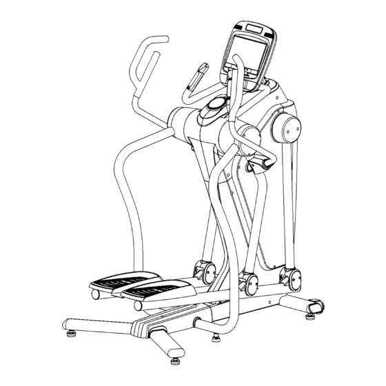
- Page 44 PRODUCT PARTS DRAWING (A)
- Page 45 PRODUCT PARTS DRAWING (B)
- Page 46 PRODUCT PARTS DRAWING (C)
Need help?
Do you have a question about the TOTAL MOTION and is the answer not in the manual?
Questions and answers