Table of Contents
Advertisement
Advertisement
Table of Contents

Subscribe to Our Youtube Channel
Related Manuals for Visionix optovue ifusion80


Summary of Contents for Visionix optovue ifusion80
- Page 1 User Manual P/N 580-48483-004 Rev B...
- Page 2 Publishing Details iFusion Please refer to the iVue 100 User’s Manual and the iCam 100 User’s Manual for full details before attempting to image patients with this device. Optovue Inc. 2800 Bayview Drive For Customer Service or Technical Support: Fremont, CA, USA, 94538 Phone: 510-623-8868 866-941-9240 U.S.
-
Page 3: Table Of Contents
TABLE OF CONTENTS Table Of Contents ........................3 Introduction ........................5 Safety Notes ........................7 2.2 Alerts for Danger, Warning, Caution, Important, and Note 2.3. Protective Packing Symbols 2.4. System Warnings Avertissements du système 2.5. Table Handling Instructions 2.6. iFusion System Label 3 Instrument Description ....................... - Page 4 6.3 iWellness With iCam Image 6.4 3-D Optic Nerve Scan with Overlay 6.5 Retina Map with Overlay Troubleshooting Product Specifications ....................51 iVue 100 Scanner & iCam 100 Please see individual manuals for details. Maintenance ........................53 Routine Care 8.1.1 Ocular (Front Objective) Lens and Cornea Lens Cleaning .......... 53 Material Required: .........................
-
Page 5: Introduction
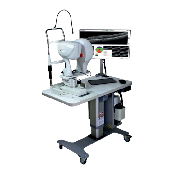
Introduction iFusion from Optovue is the combination of the non-mydriatic fundus camera, iCam 100, and the Spectral Domain Optical Coherence Tomography (SD-OCT) iVue 100 on a shuttle platform. The combination is a single retinal imaging system. iFusion is designed to provide fundus images as well as SD- OCT images of the patients. - Page 6 This page intentionally left blank. iFusion User’s Manual P/N 580-48483-004 Rev B...
-
Page 7: Safety Notes
2. Safety Notes This instrument has been developed and tested in accordance with Optovue safety standards as well as national and international regulatory guidelines to ensure a high degree of instrument safety. Please observe all safety notes and information in this manual and on the device labels. - Page 8 Indications for Use The iFusion connects the iCam (K122572) and iVue (K121739) devices via a sliding bracket mechanism (iShuttle), to facilitate switching between the two devices. The iShuttle provides position adjustment ability of the iCam or iVue device during use. The iFusion interfaces with the iCam and iVue devices to enable the operation of the iCam and iVue devices from one computer unit.
- Page 9 Equipment Classification • Type of protection against electric shock: Class 1 • Degree of protection against harmful ingress of water: IPX0 Class of operation: Continuous • • Degree of protection against electric shock of applied part (chin and forehead rests). Type B Note: The iFusion is not intended to be used as the sole diagnostic aid in disease identification, classification or management.
-
Page 10: Alerts For Danger, Warning, Caution, Important, And Note
2.2 Alerts for Danger, Warning, Caution, Important, and Note Refer to User’s Manual. Reportez-vous au livret du mode d'emploi Presence of electrical shock hazard. Voltage inside the instrument. Do not remove the instrument cover or parts. General Warning Sign WARNING indicates a potentially hazardous situation which, if not avoided, could result in death or serious injury. - Page 11 Manufacturer Optovue, Inc. 2800 Bayview Drive, Fremont, CA., USA, 94538 General mandatory action sign Authorized European Community Representative Medical Device Safety Services (MDSS) GMbH Schiffgraben 41 30175 Hannover, Germany Serial number Catalog number / part number No Sitting. Ne pas s'asseoir. No Pushing.
-
Page 12: Protective Packing Symbols
2.3. Protective Packing Symbols The protective packing symbols specify the handling requirements and the transport and storage conditions. Fragile, Handle with care Keep Dry This end up Relative Humidity (10% to 100%, including condensation) Temperature (-40 to 70 deg. C) Waste Electrical and Electronic Equipment (WEEE) Recycling Instructions When determined that the device is ready for disposal, it is... -
Page 13: System Warnings Avertissements Du Système
European Union. It is very important that customers understand and follow all laws regarding the proper decontamination and safe disposal of electrical equipment. 2.4. System Warnings Avertissements du système WARNING: THE iFusion CANNOT REPLACE CLINICAL JUDGEMENT AND IS INTENDED TO BE USED ONLY IN CONJUCTION OTHER CLINICAL TOOLS CONSIDERED TO BE THE STANDARD OF CARE FOR DIAGNOSIS OF EYE DISEASE. - Page 14 WARNING: If this equipment is modified, appropriate inspection and testing must be conducted to ensure continued safe use of the equipment. WARNING: It is recommended that no accessories other than those specifically called out in this User manual may be connected to the system. Any customer accessory equipment connected to the interface ports must be certified according to the respective IEC standards (e.g.
- Page 15 Le iFusion est un instrument médical. Le logiciel et le matériel informatique ont été conçus conformément aux normes de conception et de fabrication des appareils médicaux en vigueur aux É.-U., en Europe et ailleurs. Toute modification non autorisée du logiciel ou du matériel informatique du iFusion, ou tout ajout ou suppression d'une application de quelque manière que ce soit peut présenter un risque pour la sécurité...
- Page 16 While no acute optical radiation hazards have been identified for direct or indirect ophthalmoscopes, it is recommended that the intensity of light directed into the patient’s eye be limited to the minimum level which is necessary for diagnosis. Infants, aphakes and persons with diseased eyes will be at greater risk.
- Page 17 Alternating Current Courant alternatif. Contraindications Contre-indications This device is not designed, sold or intended for use except as indicated. Cet appareil n'est pas conçu ni vendu pour être utilisé de toute autre manière que celle spécifiée. ESD Warning: Prior to assembly, install or interconnection of the iFusion, it is recommended that any staff (i.e., biomedical engineers and health care staff) that could touch connectors identified with the ESD warning symbol undergo ESD training.
- Page 18 93/42/EEC Medical Device Directive CE Mark. Indicates this equipment contains Type B applied parts The iFusion is classified as follows: • Class I Equipment – Protection against electrical shock. • Type B – Degree of protection against electric shock of applied part (chin and forehead rests). •...
- Page 19 Étiquette d'abaissement/relèvement de la table Table Up/Down Label Pinch Warning LocationsEmplacements pour les avertissements de risque de pincement Prior to moving the iFusion system, lock iFusion base, ensure the monitor is folded down and the table is lowered to the bottom position.
- Page 20 iFusion System Locked Moving Parts Lock all wheels when not moving table. Locked Disposal: Dispose of the equipment per local regulations. Waste Electrical and Electronic Equipment (WEEE) Recycling Instructions Déchets d'équipements électriques et électroniques (DEEE) Instructions de recyclage When determined that the device is ready for disposal, it is be recycled following the policies and procedures reflecting respective country’s requirements.
- Page 21 WARNING: Do not connect the instrument with anything other than those connections specified. Otherwise, it may result in fire or electric shock. For details of purchasing accessories, please contact an Optovue representative or distributor. To avoid risk of electric shock, this equipment must only be connected to a supply main with protective earth.
- Page 22 Warning: The patient cannot touch any electrical device that is not powered by iFusion with any part of his or her body while being examined. In addition, the iFusion operator must not attempt to touch the patient and any electrical device that is not powered by iFusion at the same time while examining the patient.
- Page 23 Caution: The iVue 100 Normative database and the results displayed are based on estimated percentiles and should be used only as an aid for making clinical decisions. The results from the normative database comparison should never be used in isolation, only as one part of the entire clinical armamentarium.
- Page 24 relatively flat retinal OCT image might not reflect the true curvature of the retina. Certification To ensure full system quality, iVue 100, iCam 100 and iFusion have been manufactured in a registered ISO 9001 or 13485 facility. It has been designed and tested to be compliant (when used with the laboratory equipment requirements of applicable regulatory agencies.
- Page 25 will be required to correct the interference at their own expense. Canadian Regulations This equipment does not exceed the Class A limits for radio noise emissions from digital apparatus as set out in the radio interference regulations of the Canadian Department of Communications.
- Page 26 Software Adaptation for iFusion iFusion is a display format that allows running two separate programs easily. The addition of a tab to each program allows the user to switch from iVue 100 to iCam 100 and vice versa. The two programs use the same data accumulation and storage programming.
-
Page 27: Ifusion System Label
Service Life The service life of iVue 100 and iCam 100 is five years if specified inspections and maintenance are done 2.6. iFusion System Label sample iFusion User’s Manual P/N 580-48483-004 Rev B... - Page 28 This page intentionally left blank. iFusion User’s Manual P/N 580-48483-004 Rev B...
-
Page 29: Instrument Description
3 Instrument Description 3.1 iFusion System Configuration 3.1.1 iCam 100 Camera Head This is the main component of the iCam 100 system. It is used to provide non-mydriatic color posterior and external images of the eye. The scanner and computer communicate via two USB connections. -
Page 30: Ishuttle
3.1.5 iShuttle The iShuttle mounts to the joystick assembly using a central nut and bolt and four adjustable set screws. Only Optovue personnel should assemble the iFusion system. The iShuttle consists of a sliding metal plate with mounting devices for the iVue 100 and iCam 100 and it moves on tracks fitted with ball bearing rollers allowing it to shift left and right. - Page 31 External fixation iCam Camera light head iVue scanner head Monitor with mounting bracket Chin rest Mouse iShuttle TableTop Joystick assy. on iBase iVue Control Keyboard Box, with green system light Up/Down switch iFusion System Components iFusion User’s Manual P/N 580-48483-004 Rev B...
-
Page 32: Getting Started
Getting Started NOTE: See the iFusion installation manual, P/N 810-48474-002 Rev.B, for complete instructions. Chin Rest Chin rest extensions are required for iFusion installation. The chin rest extensions should be added to the chin rest assembly prior to use. Chin rest extensions Chin Rest Extensions Mounted Connecting iCam 100 And iVue 100 To... - Page 33 iShuttles with Unattached Cables for Original iVue (Left) And Current iVue (Right) Connect the 3-way plug in, one to each head and the base as shown in the figure below. Plugs connected iVue-100 And iCam 100 3-Way Joystick Plug Connections 6.
- Page 34 Camera head & power adapter connection Camera Head Power Cord And Power Adapter Connected 7. Insert the iVue power cord and computer power adaptor cord into the plug receptacles. 8. Attach the cables to the iVue 100 controller box. Connect the round pin cable from the chin rest, and the USB as shown in the figure below.
- Page 35 Original iVue Medical grade power supply iCam & computer Ethernet or new USB 3 Pin connecter chinrest Power switch Power cables Original iVue 100 Control Box Cabling Connections Ethernet or new USB 3 DB 9 connector for joystick chin rest Current iVue Cabling With DB 9 Joystick Chin Rest Connector iFusion User’s Manual...
-
Page 36: Starting The System
4.3 Starting the System This section describes the iFusion system startup. Power switch Power Switch on Camera Head 1. Click the power switch on the camera head to turn it 2. Turn on the iVue 100 controller power switch. 3. Start the computer by clicking the power button. After Windows has fully initialized, double click the iCam 100 icon on the desktop to launch the application. -
Page 37: Patient Imaging
5. Patient Imaging 5.1 Patient And System Position 1. Ensure that either the iCam 100 or iVue 100 head is locked into the appropriate position on the iShuttle. 2. Pull the joystick into a position all the way back toward the operator and opposite the eye to be imaged. -
Page 38: Suggested Capture Sequence
Shuttle button Position A Position B iCAM 100 And iVue 100 Positions With iShuttle Y-Axis Movement 5.2 Suggested Capture Sequence 1. With the joystick pulled back, position the iVue 100 head as the instrument to be used (with the iShuttle positioned so the iVue 100 head is over the joystick as shown in position A). -
Page 39: Beginning Image Capture
6. Pull the joystick all the way back, position iCam in front of other eye and follow the steps to capture. 5.3 Beginning Image Capture Please refer to both the iCam 100 and iVue 100 User’s Guides for information on image capture. Switch between the vertical tabs shown here to display the associated software. -
Page 40: Image Transfer From Icam
5.4 Image Transfer From iCam Fundus Image to Be Exported to iVue In REVIEW Mode To export a fundus photo: 1. Right click on the iCam 100 image. 2. Select Export to iVue. The image will be transferred to the iVue 100 scans of that patient taken on the same day. - Page 41 GCC Report With iCam 100 Image And iVue Thickness Map Overlay, Or En Face Image ONH Report With iCam Image And Thickness Map Overlay iFusion User’s Manual P/N 580-48483-004 Rev B...
- Page 42 ONH Report With Enlarged iCam 100 Image And Thickness Map Double clicking on the iCam 100 image will open the fundus photo in a separate page. Overlays can be aligned at this time. (Section 6.1) Click the red box with X in the right corner to save and close the image.
-
Page 43: Ifusion Overlay
6. iFusion Overlay Note: Please review and align all images. All scans use the same process for overlay alignment. 6.1. Overlay Alignment Process For 3-D scans the green box outlines the perimeter of the scan and the red and green cross lines can be used to view the B-scans on 3-D type exams as shown in the figure. - Page 44 Image Quality Classification Based On SQI Cutoffs “Poor” Retina SQI < 40 Glaucoma SQI < 27 Cornea SQI < 27 SQI < 32 iWellness SQI < 40 Ensure the quality is sufficient, i.e., Greater than “Poor” as shown in the table above, to continue the overlay alignment process.
- Page 45 4. The SLO image opacity can be adjusted using the two buttons located in the lower right of the popup window as shown in the figure, or by scrolling the mouse wheel. Align Overlay Toolbar 5. Compare the vessel structure of the OCT SLO image with the Fundus photo vessels by adjusting the opacity of the SLO.
-
Page 46: Retina 3-D Scan With Overlay
6.2 Retina 3-D Scan with Overlay Click on the appropriate tab for the image type to be displayed, SLO, En Face, Thickness, or iCam as shown in the upper left corner of the fundus image below. Note: Images corresponding to the other tabs are displayed below. -
Page 47: Iwellness With Icam Image
6.3 iWellness With iCam Image Note: iWellness is a separately purchased feature. The figure below shows the iWellness report screen with the iCam image (overlay is not available). 1. Click the Map tab to view the Full Retinal Thickness image. The GCC NDB reference image is superimposed on the retinal en face image. -
Page 48: 3-D Optic Nerve Scan With Overlay
6.4 3-D Optic Nerve Scan with Overlay A 3-D optic nerve scan is shown in the figure with an SLO overlay and three additional tab views: SLO, EnFace, and RNFL Thickness. SLO Overlay En Face Thickness 3-D Optic Nerve Scan With OCT SLO Overlay And Three Tab-Generated Views iFusion User’s Manual P/N 580-48483-004 Rev B... -
Page 49: Retina Map With Overlay
6.5 Retina Map with Overlay A sample Retina Map report with iCam image showing a thickness map overlay and an SLO overlay is displayed below. Retina Map Showing Thickness And SLO Overlays iFusion User’s Manual P/N 580-48483-004 Rev B... -
Page 50: Troubleshooting
Troubleshooting The image overlay troubleshooting table below deals with fundus photo and OCT issues concerning alignment problems and the associated solutions. Image Overlay Troubleshooting Table Resulting Alignment Image Problem Problem Solution Fundus Photo Difficult to find Increase/decrease Central Macula macular vessels brightness using iCam Too Dark/Light to align retina... -
Page 51: Product Specifications
Product Specifications iVue 100 Scanner & iCam 100 Please see individual manuals for details. Note: The environmental conditions that were specified for each product apply to the system as whole to ensure safety for all components and are the same as those for iVue 100 and iCam 100. iFusion User’s Manual P/N 580-48483-004 Rev B... - Page 52 This page intentionally left blank. iFusion User’s Manual P/N 580-48483-004 Rev B...
-
Page 53: Maintenance
Maintenance Please refer to the iCam 100 and iVue 100 manuals for information on individual system maintenance. Routine Care 8.1.1 Ocular (Front Objective) Lens and Cornea Lens Cleaning It is recommended that the ocular (front objective) lens of the iVue 100 be cleaned weekly or as needed. A weak OCT image or blurry video fundus image may be caused by an unclean front lens (eyelash, finger or nose prints, or excessive environmental dust or dirt). -
Page 54: Instrument Body Cleaning
8.3 Instrument Body Cleaning The iVue 100 and iCam 100 have no special protection against harmful ingress of water or other liquids (classified IPX0). To avoid damage to the instrument and cause a safety hazard, the cleaning solutions, including water, should not be directly applied to the device. -
Page 55: Index
INDEX Align Overlay Toolbar, 45 Indications for Use, 8 Calibration and intensity Maintenance, 54 image, adjusted, 45 canthus marker, 38 iShuttle eye alignment, 29 button used for positioning, Capture Sequence suggested, section, 38 Configuration, 30 CE Mark, 18 positioning, 37 chin rest Y-Axis Movement, 38 cleaning, 53... - Page 56 Proper Instrument Use, 7 Tabs Recycling, 20 software selection vertical, Retina Map with Overlay, Thickness Retina Scan with Overlay, image overlay, 46 tab, 46 Safety Notes Thickness Map Overlay section, 7 over GCC Report, 41 thickness maps image overlay, 46 in overlay alignment, 43 tab, 46 Thickness Overlay...
- Page 57 LUNEAU TECHNOLOGY SAS 2 Rue Roger Bonnet, 27340 Pont-de-l’Arche - France Tél. + 33 232 989 132 - Fax + 33 235 020 294 contact@visionix.com www.visionix.com...
Need help?
Do you have a question about the optovue ifusion80 and is the answer not in the manual?
Questions and answers