
Subscribe to Our Youtube Channel
Related Manuals for Pixii PowerShaper Indoor


Summary of Contents for Pixii PowerShaper Indoor
- Page 1 Installation Guide PowerShaper Indoor Grid tied energy storage system Document number: 14979, rev. 1.0 Issue date: 22.08.2023...
- Page 2 Commissioning and configuration of equipment should be done only by Pixii personnel or by other authorized and qualified persons. For safety reason, before you start installation, ensure all external power sources are disconnected, as well as internal battery and load fuses/breakers.
- Page 3 Wear appropriate personal protective equipment when dealing with the battery module. • Remove watches, rings, or other metal objects. • Use tools with insulated handles. • Wear rubber gloves and boots. The battery module is heavy enough to cause severe injury. Installation Guide ● PowerShaper Indoor...
- Page 4 If the battery catches fire, it will produce noxious and poisonous gases. Do not approach. Wet batteries If the battery module is wet or submerged in water, do not try to access it. Contact Pixii or your distributor for technical assistance.
- Page 5 Pixii. No part of this document may be reproduced, copied or transmitted (electronic or mechanic, including photocopying and recording) for any purpose to 3 party without the explicit written permission of Pixii. Copyright © Pixii 2023 Revision...
-
Page 6: Table Of Contents
6 Maintenance � � � � � � � � � � � � � � � � � � � � � � � � � � � � � � � � � � � � � � � � � � � � � � � 35 Installation Guide ● PowerShaper Indoor... - Page 7 6.1 System ............35 Installation Guide ● PowerShaper Indoor...
-
Page 8: Introduction
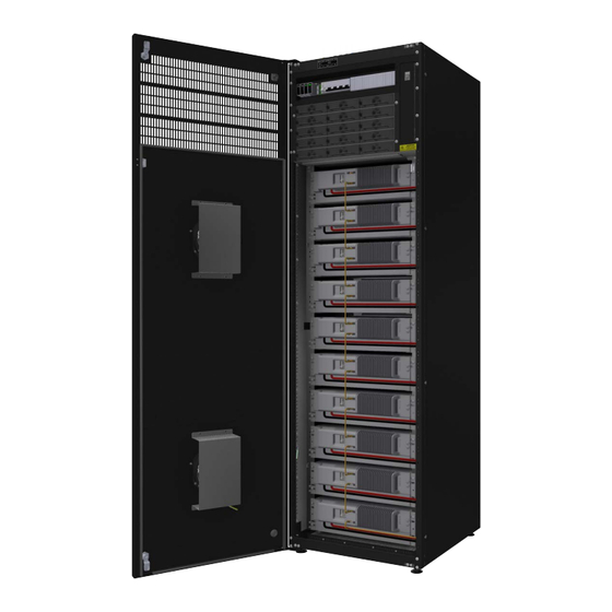
With moderate ambient temperatures or low power dissipation the fans will be running at low speed. As the ambient temperature or internal power dissipation increases the fans speed will increase. Figure 1.1 Indoor cabinet air flow diagram (side view) Installation Guide ● PowerShaper Indoor... -
Page 9: Installation Block Diagram
1�3 Installation block diagram 1�3�1 Behind the meter Figure 1.2 Single line installation block diagram - behind the meter 1�3�2 In front of the meter Figure 1.3 Single line installation block diagram - in front of the meter Installation Guide ● PowerShaper Indoor... -
Page 10: System Ratings
5.12kWh Nominal energy 4.8kWh 12.9kWh 39V-54.75V 35V-58.8V 40V-57.7V Operating voltage Max. charge/discharge 100A current Voltage fluctuations and flicker: Measured using Z 0,645 0,013Ω+j0,002Ω 0,603 test Maximum permissible network impedance, Z 0,093Ω+j0,093Ω Table 2. Electrical specifications Installation Guide ● PowerShaper Indoor... -
Page 11: Environmental Specifications
Maximum altitude 2000m Ingress protection rating IP20 Pollution degree Wet locations 25Apeak Current (inrush) Maximum output fault current 200Apeak/1ms Inverter topology Isolated Env. cat. (IEC 62477-1) Indoor conditioned Table 3. Environmental specifications * Without batteries installed. Installation Guide ● PowerShaper Indoor... -
Page 12: Mechanical Specifications
2 kg Shoto 3U battery 43 kg Polarium 3U battery 38 kg Polarium 4U battery (250Ah) 64 kg 15 kg Extension kit for 4U batteries Table 4. Dimensions and weights 1991 Figure 1.4 Mechanical specification Installation Guide ● PowerShaper Indoor... -
Page 13: Fuse List
Littelfuse Table 5. Fuse list NOTE: Please consult replacement of any fuse or circuit breaker with Pixii first. 1�5 Anti-islanding The PowerShaper incorporates both passive and active anti-islanding functionality. The passive methods included are under/over voltage, under/over frequency and rate of change of frequency detection. The active anti-islanding functionality uses the frequency shift method based on feedback from frequency variation in combination with a small reactive power perturbation. -
Page 14: Preparing Installation Site
• Recommended tools list is in chapter "Tool" on page 8 3� Prepare AC Mains supply • Correct type of AC Mains supply (TN-S) • Correct rating of AC input cables and external fuses AC Mains supply meter • Installation Guide ● PowerShaper Indoor... -
Page 15: Recommended Upstream Breaker And Input Cable
2 different types of meters. NOTE: Measured data are used at the customer's own risk. The distribution company or Pixii is not responsible for any losses resulting from its use, including losses due to errors or omissions in the data. -
Page 16: Industrial Grade Energy Meter
Preparing installation site 2�3�2 Industrial grade energy meter The Pixii system has support for an energy meters from different manufacturers. Depending on type of the meter, external measuring transformers may be required. Currently, communication via Modbus/ RTU (RS485) is supported. This means that a cable (2-wire at least) needs to be connected from the meter to the controller in the system. -
Page 17: Mechanical Installation
• Figure 3.3). By twisting cabinet feet adjust correct position (see Figure 3.1 Mount lifting lugs Figure 3.2 Fix chains or straps Figure 3.3 Adjusting the feet NOTE: Remove lifting lugs after positioning the cabinet. Installation Guide ● PowerShaper Indoor... -
Page 18: Electrical Installation
(PE), before you connect other AC input wires (phases, neutral). 4�1 Preparation Remove the front cover by releasing 4x M6x10 torx screws. Figure 4.1 Removing the front cover NOTE: Keep fixings and cover at safe place, as you need them later! Installation Guide ● PowerShaper Indoor... -
Page 19: Protective Bonding
M6 lug. Main earthing point Figure 4.2 Protective bonding NOTE: Do NOT interconnect bonding busbars in multiple cabinets in multicabinet installation. Connect separate bonding cable to each cabinet in multicabinet installation. Installation Guide ● PowerShaper Indoor... -
Page 20: Ac Mains Connection
Connect PE wire to terminals X1. Use torque T1. Conductor (CU) 1.5mm - 50mm • Connect phase wires (L1, L2, L3) and neutral wire (N) to MCB FC1. Use torque T2. - 50mm Conductor (CU) 1.0mm Figure 4.3 Mains connection Installation Guide ● PowerShaper Indoor... -
Page 21: Emergency Disconnect Switch
Electrical installation 4�4 Emergency disconnect switch Pixii system contains emergency trip device, which in case of emergency can disconnect whole system from the grid. For correct function, external switch with normally open contact and 230Vac backup power supply is required. Connect phase wire to the terminal -X5:1 and neutral wire to the terminal -X5:3. If 230Vac will be present on the terminal -X5, system will disconnect. -
Page 22: Custom Alarm Connection
All relays contacts are accessible on connector terminals -X7. Figure 4.5 Customer alarm connector terminals -X7 Installation Guide ● PowerShaper Indoor... -
Page 23: Separate Alarm
Cab. 1 Cab. 2 Cab. x Customer alarm box Figure 4.7 Common alarm (Serial) Alternative 2 (Parallel connection NO-C) . . . Cab. 1 Cab. 2 Cab. x Customer alarm box Figure 4.8 Common alarm (Parallel) Installation Guide ● PowerShaper Indoor... -
Page 24: External Communication
Electrical installation 4�6 External communication Pixii system is fully configurable through web interface. Therefore a network connection to controller is required. This can be done in different ways, depending on what type of network is present on site. The system has a Wi-Fi Access Point that can be activated to access the web interface for configuration and monitoring when at the site. -
Page 25: Ac Meter Connection
Pixii controller is not equipped with M-Bus port, therefore USB to M-Bus converter (optional kit) needs to be used. Connect it to free USB port on Pixii controller and connect Ethernet cable to RJ45 connector on converter. On meter side are 2 possible options for connecting communication cable. If only Pixii controller will be connected to AC meter, connect Ethernet cable directly to RJ45 connector on meter. -
Page 26: Installing Batteries
185mm and the rear extension kit must be installed. Bottom battery position is the same for both options. 185mm 148mm Figure 4.13 3U battery option Figure 4.14 4U battery option NOTE: Rear battery extension kit must be installed, if 4U batteries are going to be used. Installation Guide ● PowerShaper Indoor... - Page 27 (depending on the accessible holes on the mounting brackets) self tapping screws (see using torque T4. Figure 4.15 Battery positions Figure 4.16 Battery installation NOTE: Empty battery positions (if any) must be covered by blank panels to obtain correct air flow inside the cabinet. Installation Guide ● PowerShaper Indoor...
- Page 28 NOTE: Insert termination plug to the last unused Modbus port. See details in Figure 4.17 NOTE: Ensure, that battery cables are not in/not colliding with air gap between the batteries. It could cause overheating problems. Installation Guide ● PowerShaper Indoor...
-
Page 29: Shoto
Figure 4.21 Battery installation NOTE: Empty battery positions, if any, must be covered by blank panels to obtain correct air flow inside the cabinet. NOTE: Use attached self tapping screws for fixing batteries to the battery shelves. Installation Guide ● PowerShaper Indoor... - Page 30 NOTE: Ensure, that battery cables are NOT colliding with battery breakers above the battery terminals. NOTE: Ensure, that battery cables are not in/not colliding with air gap between the batteries. It could cause overheating problems. Installation Guide ● PowerShaper Indoor...
- Page 31 Table 6. Code switch address NOTE: Start addressing the batteries from first battery #1 at the bottom and continue to the top. NOTE: After complete installation of batteries, do NOT forget to mount all covers back. Installation Guide ● PowerShaper Indoor...
-
Page 32: Battery Com Converter
Proper configuration of converter (-TF1) is necessary to secure the correct communication with various type of batteries. Follow the tables below to set the DIP switches in the right positions. Figure 4.24 Battery Com converter (-TF1) Polarium batteries configuration Shoto batteries configuration table table Installation Guide ● PowerShaper Indoor... -
Page 33: Power Modules
Electrical installation 4�9 Power modules The last step in the system installation is to install Pixii modules. Each power shelf contains 3 positions for modules. Each position is wired to different phase, starting with L1 from the left. To secure correct 3-phase operation, all 3 modules must be installed in every used shelf. -
Page 34: System Label
4�10 System label Pixii system is marked with 2 system labels. One label is located on the outside of the cabinet (right hand side seen from the front), and one is located inside the cabinet on the left side of the battery racks. -
Page 35: Commissioning Procedure
Do not limit the evaluation to only those points. NOTE: For repair and replacement use only original Pixii parts and in accordance with technical specification provided by Pixii. Use of non-original parts may void the warranty provided by Pixii.
Need help?
Do you have a question about the PowerShaper Indoor and is the answer not in the manual?
Questions and answers